Encapsulated magnet assembly, method of purging a gap rotary machine and oil/gas plant description

Inactive Publication Date: 2015-10-15
NUOVO PIGNONE SPA
View PDF3 Cites 0 Cited by
  • Summary
  • Abstract
  • Description
  • Claims
  • Application Information

AI Technical Summary

Benefits of technology

[0043]Encapsulated magnet assemblies or magnetic bearings according to some embodiments of the present invention make it possible to provide an oil/gas plant with extremely high rotation speed rotary machines. Furthermore, the encapsulated magnet assem

Problems solved by technology

Due to the relative motion between the rotor and the stator the fluid in the gap tends to absorb power from the prime mover of the rotor thus reducing the overall efficiency of the machine.
Windage loss is linearly proportional to the density of the fluid, the axial length of the bearing, the gap between rotor and stator; Windage loss is also proportional to the fourth power of the radius of the rotor o

Method used


Image

  • Encapsulated  magnet  assembly,  method  of  purging  a  gap rotary  machine  and  oil/gas  plant description
  • Encapsulated  magnet  assembly,  method  of  purging  a  gap rotary  machine  and  oil/gas  plant description
  • Encapsulated  magnet  assembly,  method  of  purging  a  gap rotary  machine  and  oil/gas  plant description

Examples


Example

[0054]The following description of the exemplary embodiments refers to magnetic bearings as shown in the accompanying drawings. The same reference numbers in different drawings identify the same or similar elements. The following detailed description does not limit the invention; instead, the scope of the invention is defined by the appended claims.

[0055]It is to be noted that in the accompanying drawings sometimes sizes have been exaggerated for the sake of clarity; in other words they are not perfectly in scale between each other.

[0056]Reference throughout the specification to “one embodiment” or “an embodiment” means that a particular feature, structure, or characteristic described in connection with an embodiment is included in at least one embodiment of the subject matter disclosed. Thus, the appearance of the phrases “in one embodiment” or “in an embodiment” in various places throughout the specification is not necessarily referring to the same embodiment. Further, the particu...


PUM


Abstract

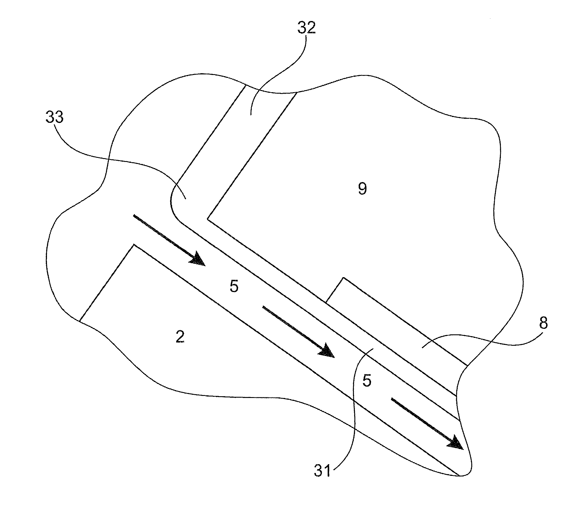
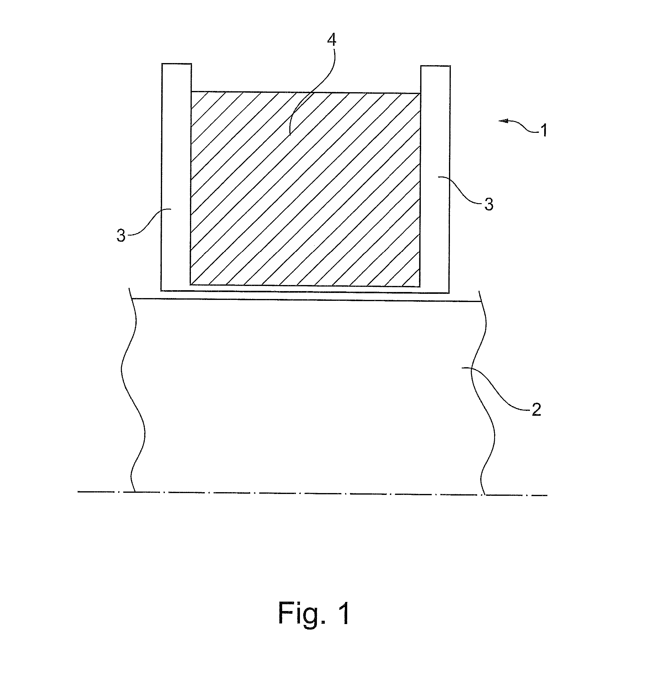
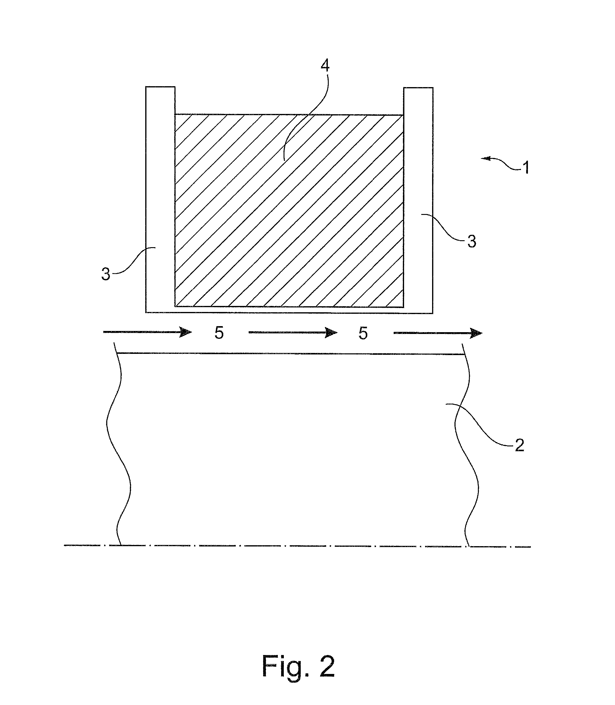
A encapsulated magnet assembly includes at least one pole piece and an encapsulation housing. At least one portion of the encapsulation housing is adjacent to the at least one pole piece. At least one recess is provided in the encapsulation housing next to the housing portion for establishing fluid flow. The at least one recess is so shaped as to facilitate the fluid flow,

Description

TECHNICAL FIELD[0001]Embodiments of the subject matter disclosed herein generally relate to encapsulated magnet assemblies, methods of purging a gap between an encapsulation housing of a magnet assembly and a part of machine, rotary machines, and oil / gas plants. Such magnet assemblies may be used for magnetically bearing parts of machines.BACKGROUND ART[0002]A magnetic bearing is a bearing which supports a load using magnetic levitation. Magnetic bearings support machines without physical contact; for example, they can levitate a rotating shaft of a machine and permit relative motion with very low friction and no mechanical wear. A magnetic bearing comprises a stator assembly and a rotor assembly separated by a gap, often an air gap and more in general a gas gap; the stator assembly usually comprises pole pieces and coils. Such bearings are known for example from U.S. Pat. No. 5,095,237.[0003]It is to be noted that the rotor assembly may be part of the rotary machine being, for exam...

Claims


Application Information

Patent Timeline
IPC IPC(8): H02K1/32H02K7/09
CPCH02K7/09H02K1/32F16C32/047F16C37/005F16C32/048H02K5/128F16C32/04
Inventor LOMBARDI, LUCA
Owner NUOVO PIGNONE SPA
Why Eureka
Try Eureka