Oil collector

Active Publication Date: 2015-12-03
M&L PATENT OY
View PDF5 Cites 0 Cited by
  • Summary
  • Abstract
  • Description
  • Claims
  • Application Information

AI Technical Summary

Benefits of technology

[0013]The oil collector according to the invention has considerable advantages as compared to the prior art. The brush structure according to the invention collects oil to the bristles better than the radial bristles, the oil is kept better attached to the bristles up to their removal and the bristles do not let ice pass through, which makes the collecting outcome better. Thus, by the brush structure according to the invention, the speed of

Problems solved by technology

However, problems are caused in the prior art by the operation of the brushes particularly in icy oil.
Furthermore, the oil retention capacity of th

Method used


Image

  • Oil collector
  • Oil collector
  • Oil collector

Examples


Example

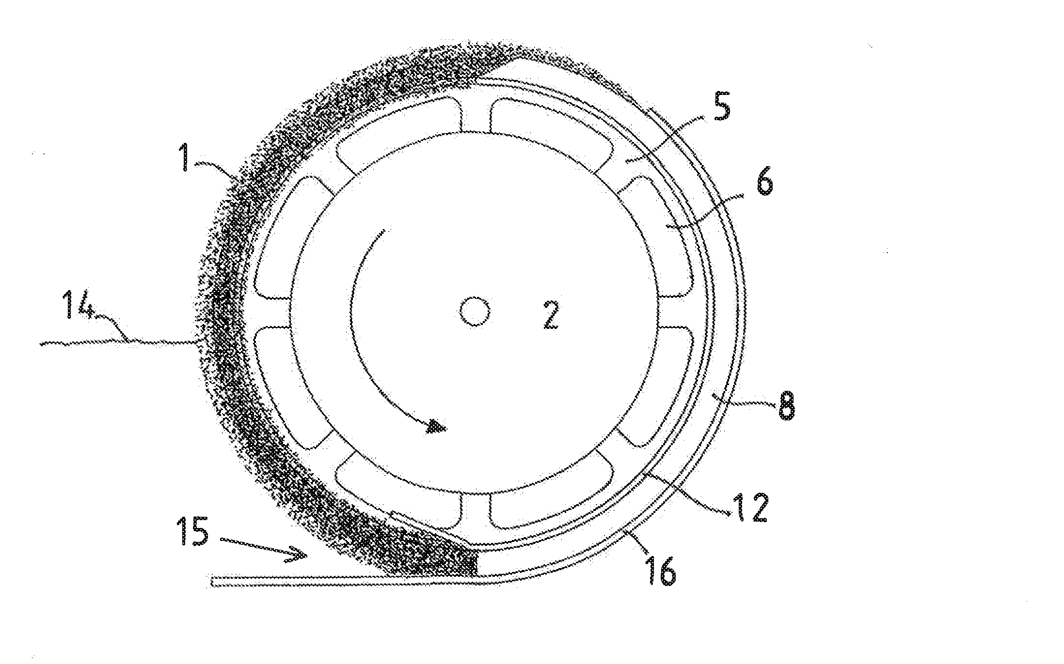
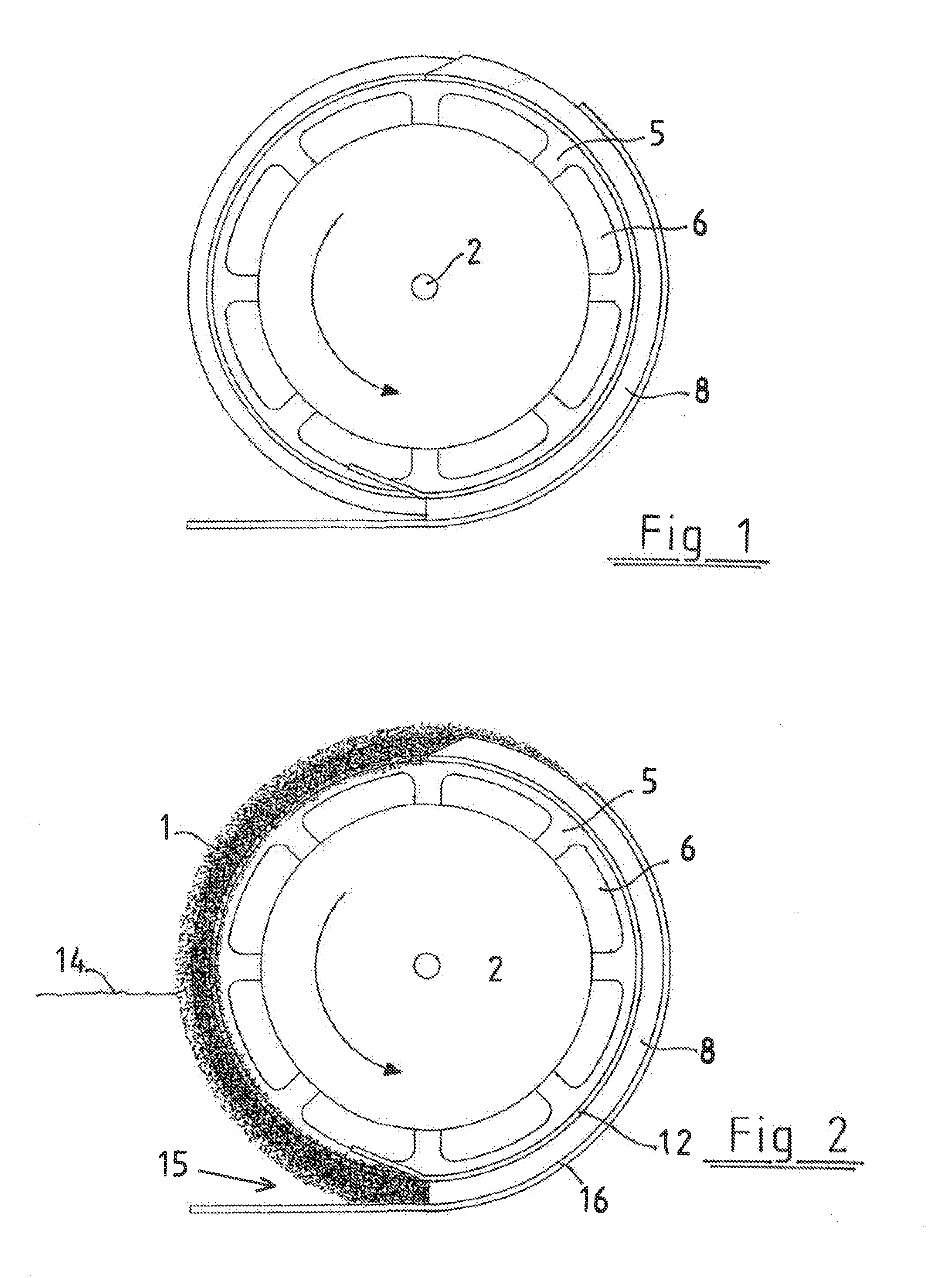
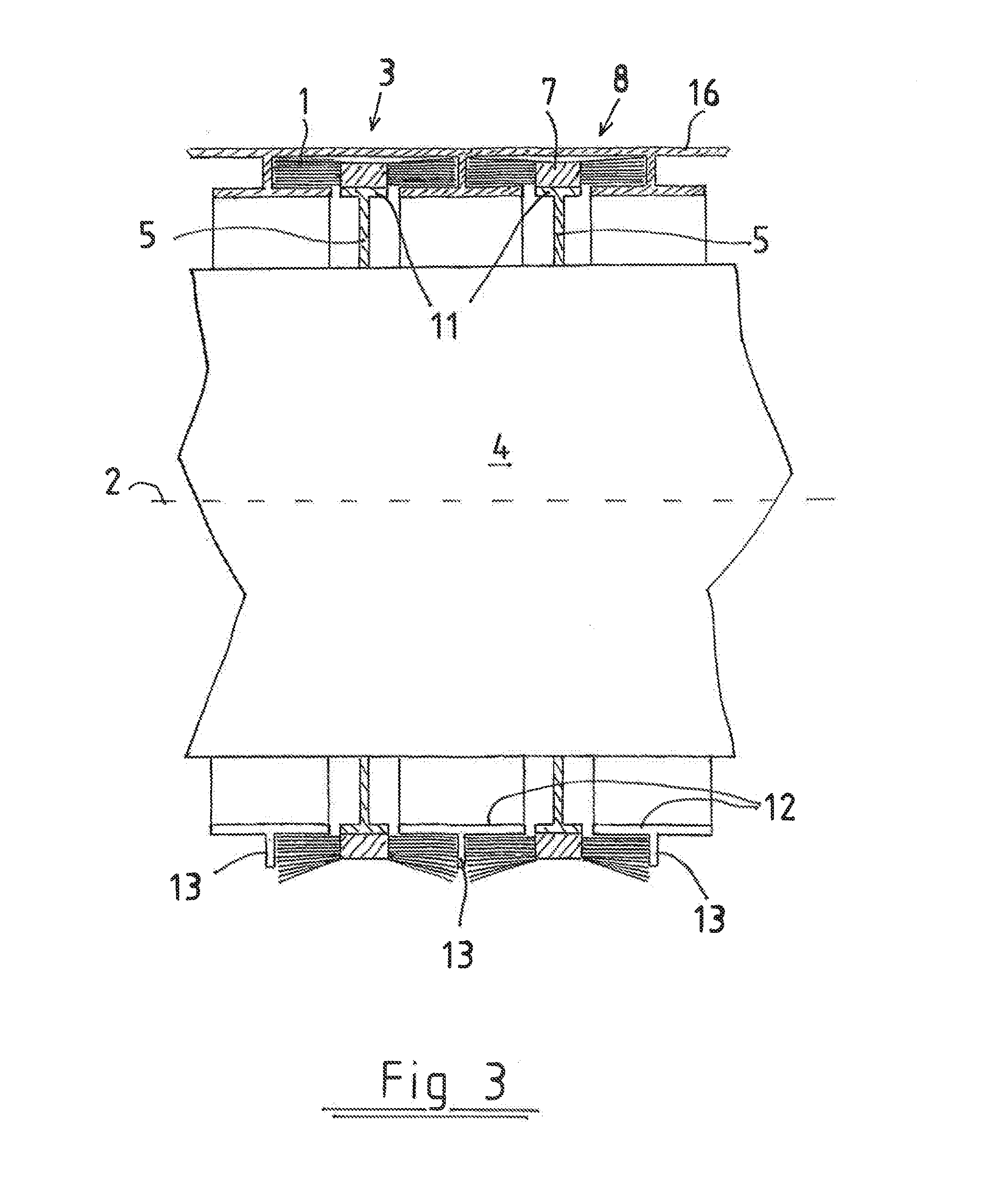
[0021]FIG. 1-3 illustrate the essential parts of one oil collector according to the invention. The oil collector includes a solid drum 4 with a horizontal shaft 2. In other words, the shaft 2 is parallel to the surface of water. A circular flange, i.e. a brush support 5, is mounted on the outer surface of the drum to circulate the drum. There is an appropriate number of brush supports spaced apart from one another in the axial direction. A plate-type attachment flange 11 that is perpendicular to the brush support circulates the outer perimeter of the brush support. The brush support 5 is provided, substantially over its entire length, with flow openings 6 allowing the water axially to flow on the surface of the drum 4.

[0022]A brush body 7 of the brush 3 is attached to the attachment flange 1 and circularly extends around the entire structure. Bristles are attached to the brush body 7 over the entire length of the perimeter thereof on two opposed sides thereof such that the bristles ...


PUM


Abstract

The invention relates to an oil collector including a brush (3), provided with substantially straight bristles (1) and a horizontal shaft (2), and a cleaning structure in the upper part of the brush for cleaning the brush from oil. According to the invention, the bristles (1) of the brush (3) are substantially parallel to the horizontal shaft (2).

Description

FIELD OF THE INVENTION[0001]The invention relates to an oil collector as defined in the preamble of claim 1.BACKGROUND OF THE INVENTION[0002]A traditional means that has been tried and found to be relatively good in collecting oil from water is a skimmer, i.e. a brush rotated partly in water and partly above the water, wherein the oil adheres to the bristles of the brush and is carried out of the water with the rotation of the brush. The bristles are then cleaned above the water by an appropriate comb structure before rolling once again back into the oily water. A structure based on bristles may be formed by one drum-type brush or alternatively by a brush cassette wherein a belt provided with bristles circulates between two rotating rolls.[0003]However, problems are caused in the prior art by the operation of the brushes particularly in icy oil. Bits of ice are easily caught between radially extending bristles but are not adhered to the bristles; instead, they slip out, bringing alo...

Claims


Application Information

Patent Timeline
IPC IPC(8): E02B15/04
CPCE02B15/048E02B15/103E02B15/102E02B15/104Y02A20/204
Inventor LUNDIN, LARS INGRAM
Owner M&L PATENT OY
Why Eureka
Try Eureka