Alignment template goodness qualification method

Inactive Publication Date: 2006-07-06
DRVISION TECH
View PDF6 Cites 17 Cited by
  • Summary
  • Abstract
  • Description
  • Claims
  • Application Information

AI Technical Summary

Benefits of technology

[0008] This invention resolves the template quality problem by performing alignment template goodness measurement and qualification for manually selected or automatically generated alignment template(s). The alignment template goodness qualification method of this invention performs measurement and qualification of the signal content, spatial discrimination, and pattern ambiguity of the alignment template(s). If the selected template(s) cannot be qualified, alternative templates could be selected either automatically or manually.
[0009] The primary objective of this invention is to qualify the selected template for good alignment outcome. The second objective of this invention is to allow the selection of alternative templates for better alignment outcome. The third objective of the invention is to select good templates to achieve best spatial discrimination. The fourth objective of the invention is to select templates containing good signal content for stable and accurate search result. The fifth objective of the invention is to select good templates with unambiguous patterns for stable and accurate search result. The sixth objective of the invention is to provide quant

Problems solved by technology

This process limits the flexibility of the alignment options and increases system complexity and cost because the marks have to be made on each objects.
The mark making process is challenging when fine alignment is required since the variations of the created marks without rigorous control may exceed the required fine precision.
However, the images could includ

Method used


Image

  • Alignment template goodness qualification method
  • Alignment template goodness qualification method
  • Alignment template goodness qualification method

Examples


Example

[0031] I. Application Scenario

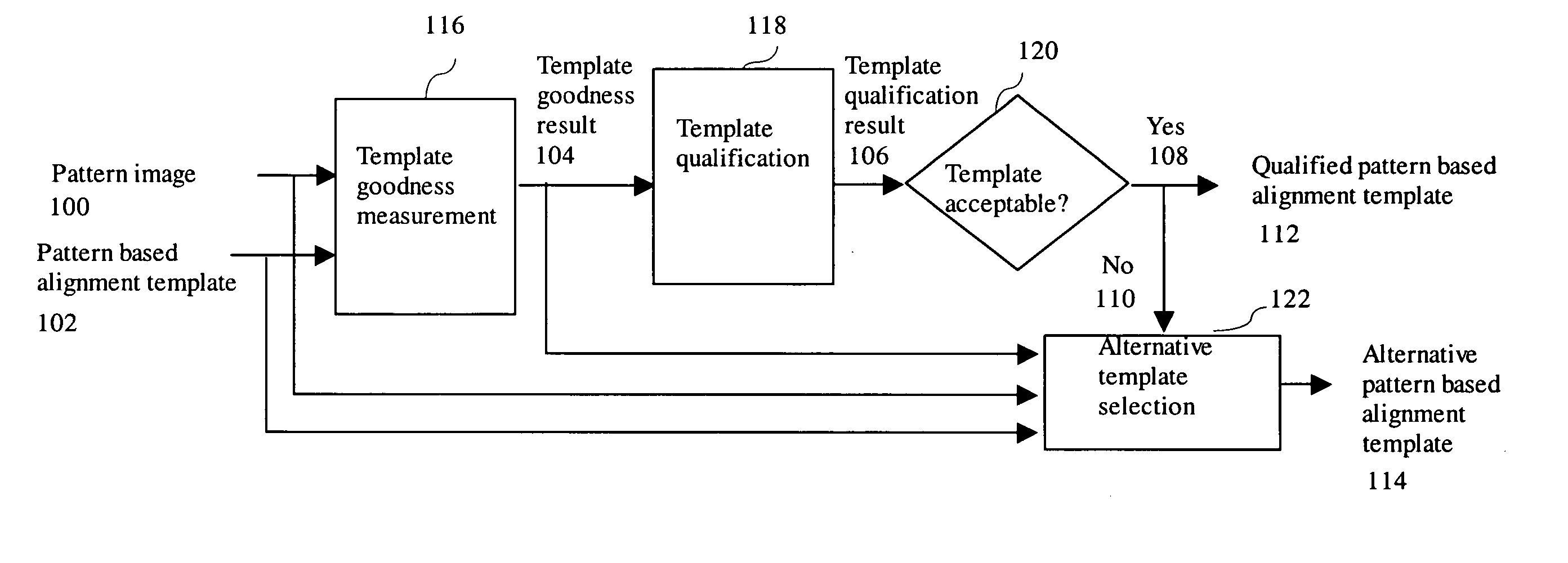
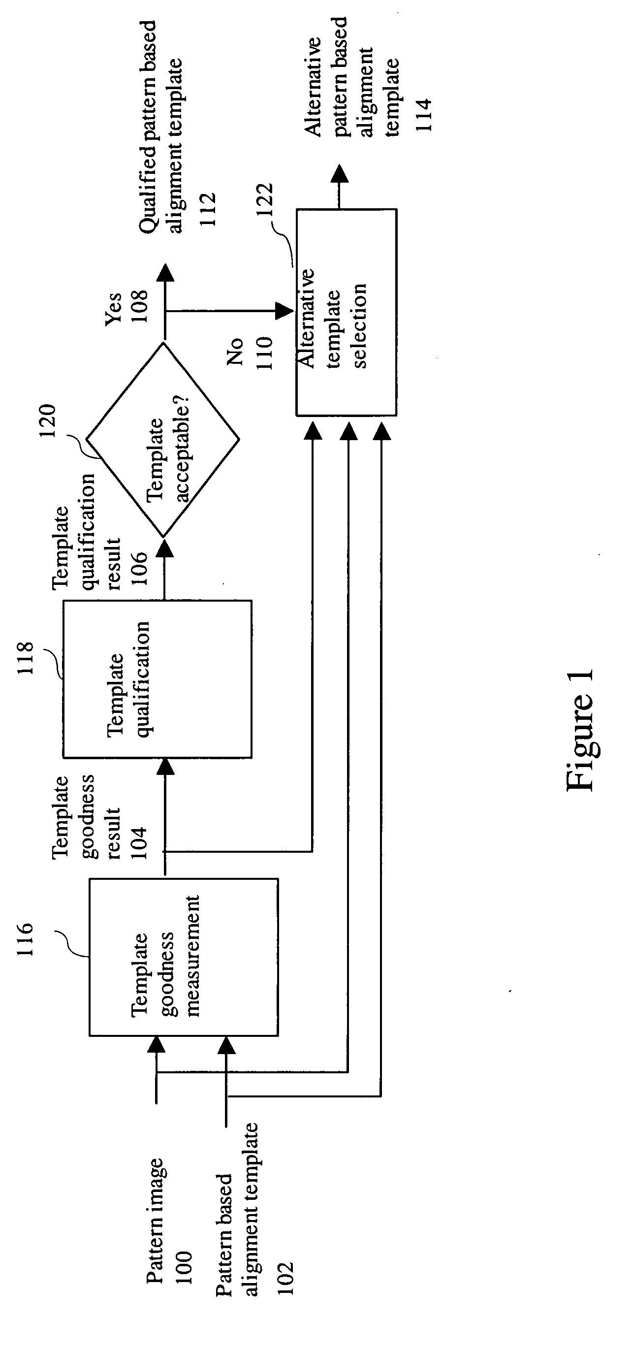
[0032]FIG. 1 shows the processing flow for the alignment template goodness qualification application scenario in one embodiment of the invention. As shown in FIG. 1, a pattern image 100 and pattern based alignment template 102 are inputted to a template goodness measurement stage 116. The template goodness measurement stage 116 processes the pattern image 100 and the pattern based alignment template 102 to generate a template goodness result 104 output. The template goodness result 104 is processed by a template qualification stage 118 that uses the template goodness result 104 to qualify the template and generates a template qualification result 106 output. If the template qualification result is acceptable 120 (‘Yes’ status 108), the pattern based alignment template 102 is outputted as the qualified pattern based alignment template 112. Otherwise, if the template qualification result is unacceptable,120 (‘No’ status 110), an alternative template sele...


PUM


Abstract

An alignment template goodness qualification method receives a pattern image and a pattern based alignment template and performs template goodness measurement using the pattern image and the pattern based alignment template to generate template goodness result output. A template qualification is performed using the template goodness result to generate template qualification result output. If the template qualification result is acceptable, the pattern based alignment template is outputted as the qualified pattern based alignment template. Otherwise, an alternative template selection is performed using the pattern image, the pattern based alignment template and the template goodness result to generate alternative pattern based alignment template output. The template goodness measurements include signal content measurement, spatial discrimination measurement and pattern ambiguity measurement.

Description

TECHNICAL FIELD [0001] This invention relates to the qualification of the template patterns for the automated alignment of objects. The patterns for alignment match are the design structures of the objects rather than pre-defined fiducial marks. BACKGROUND OF THE INVENTION [0002] Many industrial applications such as electronic assembly and semiconductor manufacturing processes require automatic alignment of objects such as electronic components, printed circuit board or wafers. Most of the prior-art approaches use predefined fiducial marks for alignment. This requires the design and make of the marks on the objects being aligned. This process limits the flexibility of the alignment options and increases system complexity and cost because the marks have to be made on each objects. The mark making process is challenging when fine alignment is required since the variations of the created marks without rigorous control may exceed the required fine precision. [0003] On the other hand, th...

Claims


Application Information

Patent Timeline
IPC IPC(8): G06K9/00
CPCG06K9/6204G06T7/0006G06T7/0028G06T7/0044G06T2207/30148H05K3/0008G06T7/33G06T7/74G06V10/752
Inventor LEE, SHIH-JONG J.CHENG, YUHUI Y.C.OH, SEHONAKAJIMA, SHINICHIKOKUMAI, YUJI
Owner DRVISION TECH
Why Eureka
Try Eureka