Method for setting the tooth face position of a gear wheel

Inactive Publication Date: 2013-06-04
JAHNEL KESTERMANN GETRIEBEWERKE
View PDF10 Cites 0 Cited by
  • Summary
  • Abstract
  • Description
  • Claims
  • Application Information

AI Technical Summary

Benefits of technology

[0024]Advantageously, the gear wheel of a pinion shaft may also be skewed. Skewing allows higher load bearing capacity and higher r

Problems solved by technology

Deviations due to manual intervention have also been observed, caused in the assembly process when the components manual joined.
This type of non-positive connections does no longer allow larger corrections of the position of the tooth faces.
The post-processing is associated with significant costs.
Although it is theoretically possible to leave a sizeable amount of overmeasure on the tooth faces, which would reduce the risk that the tooth faces are ground too thin if the gear wheel havi

Method used


Image

  • Method for setting the tooth face position of a gear wheel
  • Method for setting the tooth face position of a gear wheel
  • Method for setting the tooth face position of a gear wheel

Examples


Example

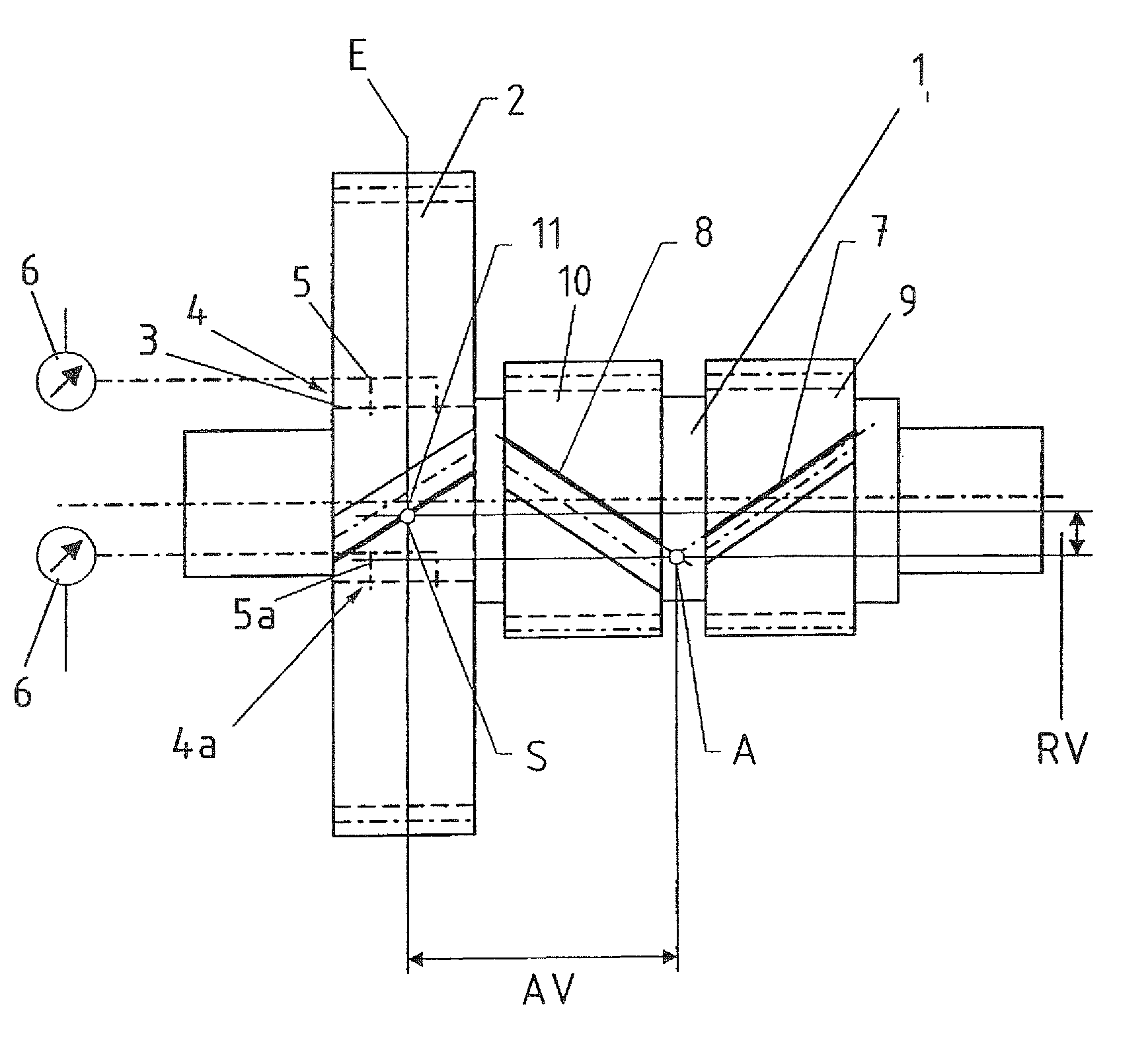
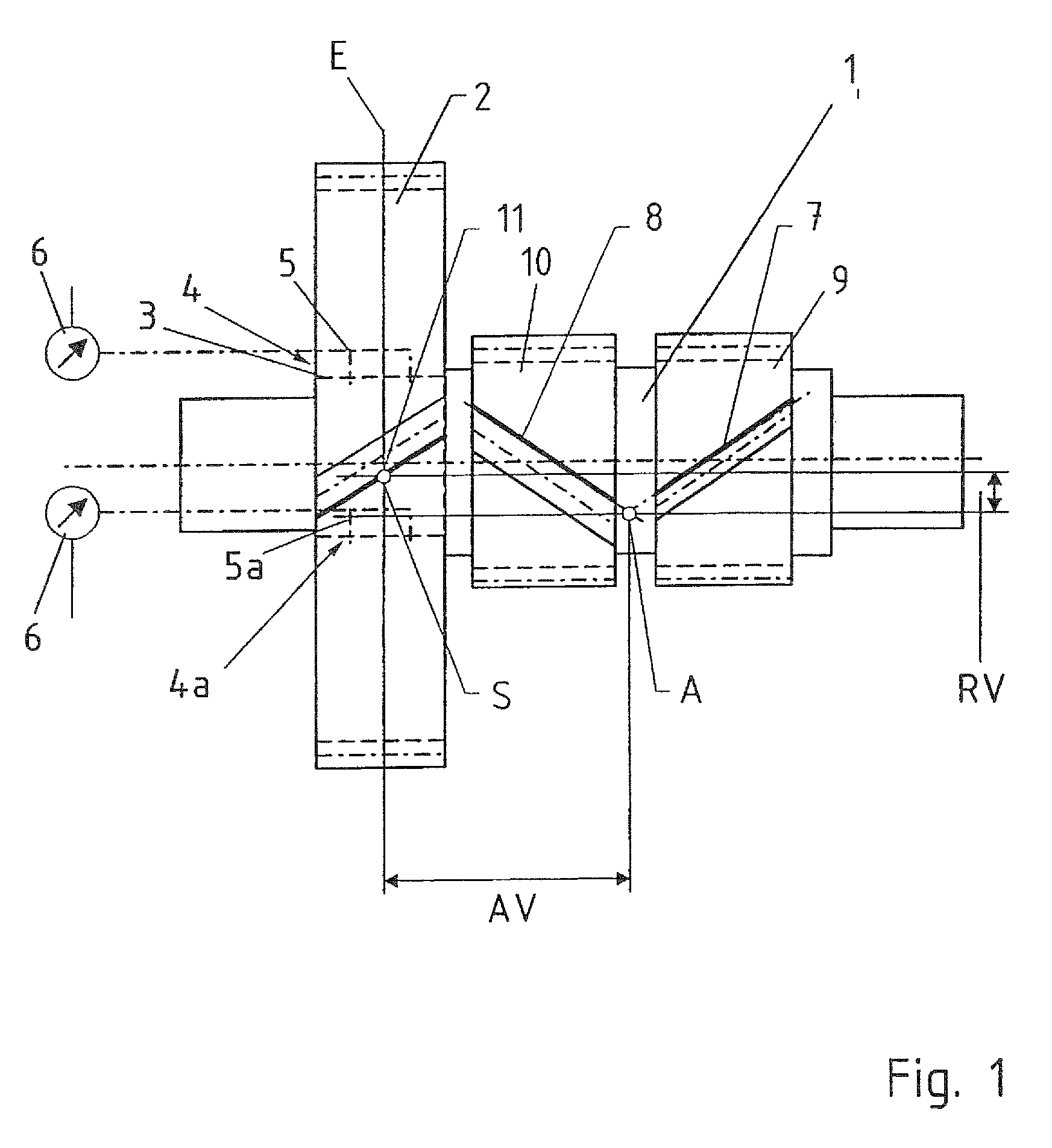
[0028]FIG. 1 shows a multiple-toothed pinion shaft. The tooth structure has a double-skew. In addition, a gear wheel 2 is arranged on the pinion shaft 1. The gear wheel 2 is non-positively connected with the pinion shaft 1. The connection is formed by shrink-fitting the gear wheel 2 on the shaft seat 3. In addition, a hydraulic press fit 4, 4a is formed between the shaft seat 3 and the gear wheel 2. The alternative embodiment of the hydraulic press fit illustrated in the upper part of the image plane includes hydraulic channels 5 arranged in the gear wheel 2, which are provided to conduct a hydraulic fluid with a pumping unit 6 into the joint region between the gear wheel 2 and the shaft seat 3.

[0029]The alternative embodiment of a hydraulic press fit 4a illustrated in the lower half of the image has hydraulic channels 5a formed in the pinion shaft 1 and / or in the shaft seat 3 of the pinion shaft 1. Pressure can also be applied to these hydraulic channels 5a with a pumping unit 6 so...


PUM


Abstract

The invention relates to a method for setting the tooth face position of a gear wheel (2), which is non-positively connected to a double-skewed pinion shaft (1). A hydraulic press fit (4, 4a) is formed between the gear wheel (2) and pinion shaft (1) for relieving a non-positive connection of the gear wheel (2) shrink-fitted onto the pinion shaft (1). The setting is carried out by determining a tooth face apex point (A) of the double-skew of the pinion shaft (1). A radial plane (E) with a predetermined axial offset (AV) from the tooth face apex point (A) and a radial offset (RV) with respect to the tooth face apex point (A) are defined. The intersecting point (S) of a tooth face (11) of the gear wheel (2) must be located with the predetermined radial offset (RV) in the radial plane (E). Such a pinion shaft (1) is used, in particular, in a power-splitting spur gearbox (12), wherein an input shaft is in multiple engagement with several pinion shafts (1) via a double-skew, wherein the gear wheels (2) of the pinion shafts (1) are in turn in multiple engagement with a common driven shaft (15).

Description

CROSS-REFERENCES TO RELATED APPLICATIONS[0001]This application is the U.S. National Stage of International Application No. PCT / DE2008 / 002132, filed Dec. 18, 2008, which designated the United States and has been published as International Publication No. WO 2009 / 112003 and which claims the priority of German Patent Application, Serial No. 10 2008 013 983.1, filed Mar. 12, 2008, pursuant to 35 U.S.C. 119(a)-(d).BACKGROUND OF THE INVENTION[0002]The invention relates to a method for setting the tooth face position of a gear wheel, which is non-positively connected to a double-skewed pinion shaft, the use of such pinion shaft in a torque-split spur gear, as well as a spur gear with such pinion shaft.[0003]It is known to assemble pinion shafts, on which a gear wheel with a larger diameter is to be arranged, not from a single component, but rather from several components. The gear wheel can hereby be affixed on the pinion shaft positively or non-positively. In a non-releasable, non-positiv...

Claims


Application Information

Patent Timeline
IPC IPC(8): F16H1/20
CPCB23P11/022F16D1/0858F16D1/12F16H1/22F16H57/12F16H1/48Y10T74/19628F16H2057/125Y10T29/49464Y10T74/19679
Inventor SCHAFER, LOTHARWAWRO, HORST
Owner JAHNEL KESTERMANN GETRIEBEWERKE
Why Eureka
Try Eureka