
Filled solid tire for low speed heavy duty vehicle

A low-speed heavy-duty, solid tire technology, applied to wheels, vehicle parts, non-pneumatic tires, etc., can solve the problems of low permanent deformation, poor handling, and weakened tire compression performance and mechanical strength

Active Publication Date: 2021-03-16
芜湖集拓实心胎有限公司
View PDF20 Cites 0 Cited by
  • Summary
  • Abstract
  • Description
  • Claims
  • Application Information

AI Technical Summary

Problems solved by technology

[0002] A solid tire is a kind of tire corresponding to a pneumatic tire. Its carcass is solid. It does not use cords as a skeleton and does not need to be inflated, so it does not need an inner tube or an airtight layer. The earliest tires are solid tires. Low-speed high-load vehicles or machinery are also used for fixed-position machinery. Solid tires are generally divided into two types: bonded and non-bonded. Tires on rims and solid tires are generally used under high loads. The rubber compound is required to have sufficient pressure resistance and wear resistance, high enough constant elongation stress, high hardness, low permanent deformation and good resistance. Abrasion resistance, solid tire is an industrial tire suitable for vehicles operating under low-speed, high-load and harsh conditions. Its safety, durability, and economy are significantly better than pneumatic tires, and are widely used in various industrial vehicles and military vehicles. , construction machinery, port and airport trailers and other fields, the main production material is made of a special rubber material, except for a small hollow in the middle to maintain the center of gravity, all of them are solid, so that the tires made can play anti-nail , anti-bullet, anti-mine, and anti-flammable bottles are very popular among police officers, but solid tires are very heavy, and the maneuverability is not very good after being mounted on a car. The existing filled solid tires usually fill the inner cavity of the tire with polyurethane
[0003] The existing filled solid tire is filled with polyurethane in the inner cavity of the tire, which has the advantage that it will not cause a tire blowout, and the safety is greatly improved, but the disadvantages are: the tire has poor shock absorption performance and cannot play a good shock absorption effect At the same time, because the inside of the tire is hollow, the tire's compressive performance and mechanical strength are weakened, especially the strength on both sides of the tire is low, and the compressive performance is poor

Method used


Image

  • Filled solid tire for low speed heavy duty vehicle
  • Filled solid tire for low speed heavy duty vehicle
  • Filled solid tire for low speed heavy duty vehicle

Examples


Embodiment 1

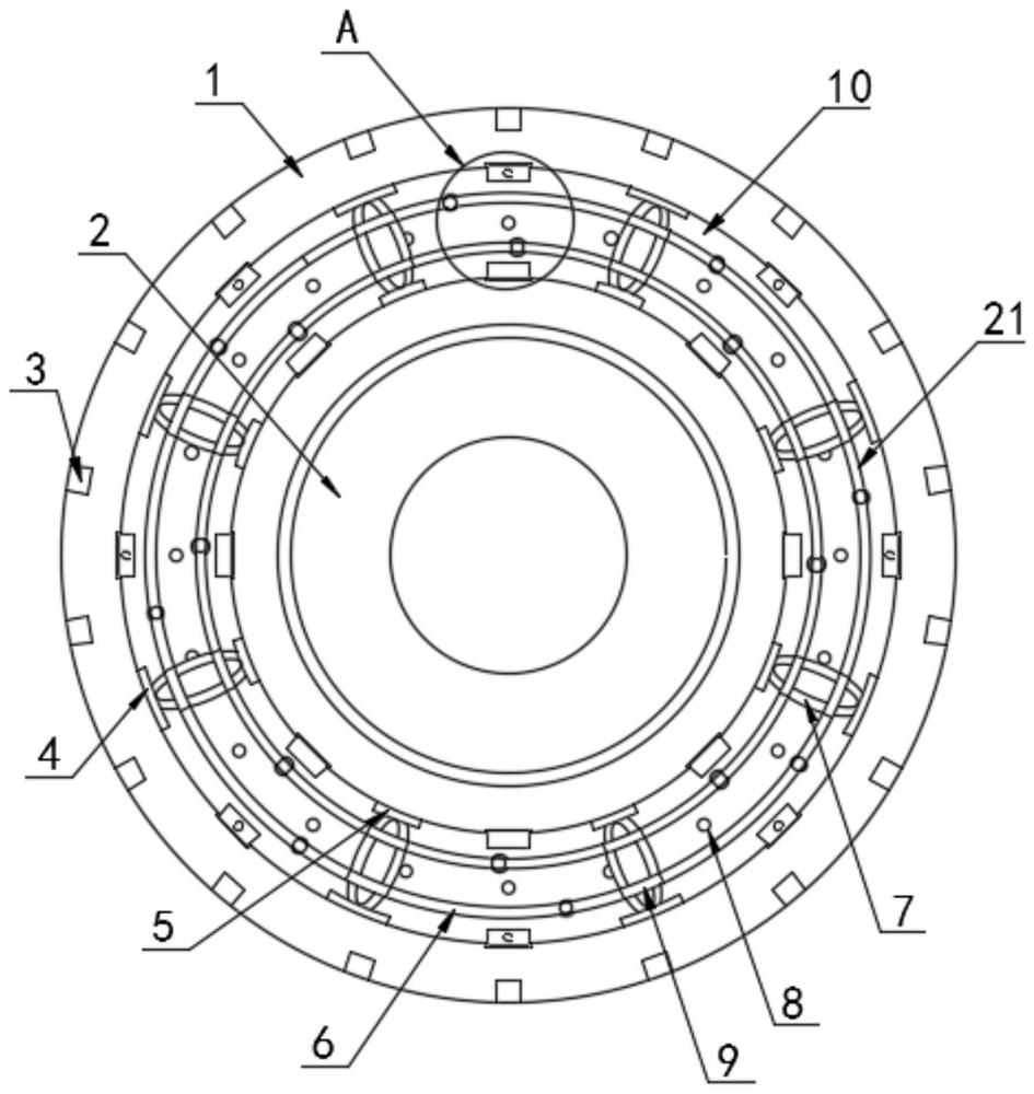
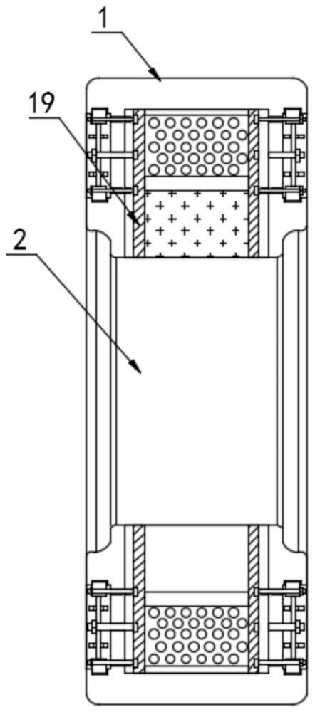
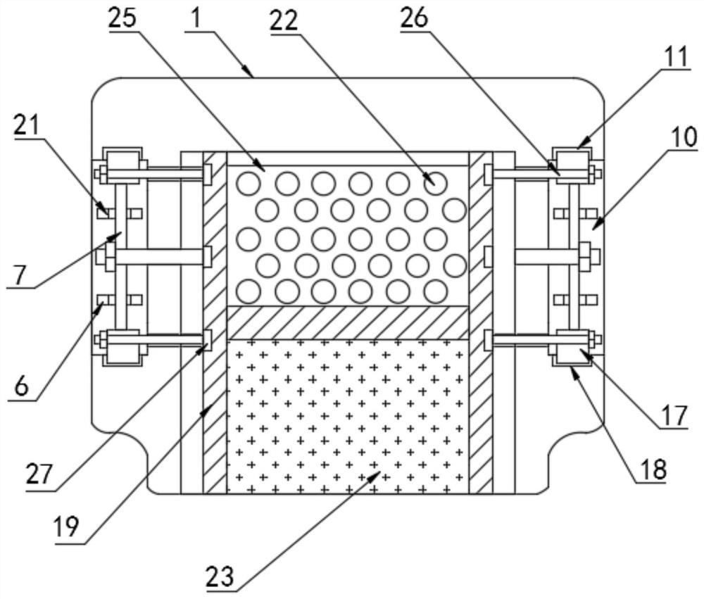
[0029] Refer to the attached Figure 1-7 A filled solid tire for low-speed heavy-duty vehicles in this embodiment includes a tire entity 1 and a hub 2, the inner wall of the top of the hub 2 is socketed on the tire entity 1, and a concave hole is opened on the tire entity 1. Groove 10, the inner wall of the top of the groove 10 is provided with a rectangular groove 11, the inner wall of the bottom of the groove 10 is provided with a rectangular groove 2 18, and the circumference of the side wall of the tire entity 1 is evenly provided with ventilation and cooling holes 8 and the fixing hole 12, the rectangular groove one 11 and the rectangular groove two 18 inner walls insert the clamping block 17, the inner wall of the clamping block 17 is threadedly connected to the pin rod 26, and the pin rod 26 is away from one end thread of the clamping block 17 Connect the reinforcing rod 29, the reinforcing rod 29 is provided with an internal thread hole 27, one end of the reinforcing r...

Embodiment 2

[0038] Refer to the attached Figure 8 , the difference from Embodiment 1 is: the tire entity 1 is also provided with a rectangular heat dissipation groove 30, and the rectangular heat dissipation groove 30 is provided with two groups, and the two groups of rectangular heat dissipation grooves 30 are located on the front side of the tire entity 1. In the middle: the function of the rectangular cooling groove 30 is to enable the tire entity 1 to dissipate heat quickly, and to increase the grip performance of the tire entity 1 to prevent skidding;

[0039] The specific implementation scenarios are:

[0040] Compared with Embodiment 1, when using the present invention, the outer ring 19 is placed in the accommodation chamber 25 of the tire entity 1, and the upper side of the accommodation chamber 25 of the tire entity 1 is filled with the cushioning soft rubber elastic ball 22, and through the internal thread The hole 27 is threaded with the pin rod 26 to connect the outer ring ...


PUM

PropertyMeasurementUnit
Widthaaaaaaaaaa
Heightaaaaaaaaaa

Abstract

The invention provides a filled solid tire for a low speed heavy duty vehicle. According to the technical scheme, the filled solid tire for the low-speed heavy-duty vehicle comprises a tire solid bodyand a hub, the inner wall of the top of the hub is connected with the tire solid body in a sleeving mode, a groove is formed in the tire solid body, a first rectangular groove is formed in the innerwall of the top of the groove, a second rectangular groove is formed in the inner wall of the bottom of the groove, and ventilation and heat dissipation holes and fixing holes are evenly formed in thecircumference of the side wall of the tire solid body. The filled solid tire has the beneficial effects that the inner wall of the groove is supported by an outer top plate and an inner top plate, sothat the compression resistance of the two sides of the tire solid body is enhanced; the inner wall of a containing cavity is effectively supported by an outer ring, reinforcing rods and an inner ring, the compression resistance of the tire solid body is improved, mounting and dismounting are convenient, the damping performance of the tire solid body is effectively enhanced through damping ringsand buffering soft rubber elastic balls, the damping rings play a role in supporting the tire solid body in the damping process, and the tire solid body maintains high gravity bearing performance.

Description

technical field [0001] The invention relates to the technical field of filled solid tires, in particular to a filled solid tire for low-speed heavy-duty vehicles. Background technique [0002] A solid tire is a kind of tire corresponding to a pneumatic tire. Its carcass is solid. It does not use cords as a skeleton and does not need to be inflated, so it does not need an inner tube or an airtight layer. The earliest tires are solid tires. Low-speed high-load vehicles or machinery are also used for fixed-position machinery. Solid tires are generally divided into two types: bonded and non-bonded. Tires on rims and solid tires are generally used under high loads. The rubber compound is required to have sufficient pressure resistance and wear resistance, high enough constant elongation stress, high hardness, low permanent deformation and good resistance. Abrasion resistance, solid tire is an industrial tire suitable for vehicles operating under low-speed, high-load and harsh co...

Claims


Application Information

Patent Timeline
IPC IPC(8): B60C7/10B60C7/14B60B9/00B60C11/03
CPCB60C7/10B60C7/14B60B9/00B60C11/03B60C7/146Y02T10/86
Inventor 王化勇吴喜林梁云峰
Owner 芜湖集拓实心胎有限公司
Learn More