Brake tube connector

a technology of brake tube and connector, which is applied in the direction of hose connection, braking system, braking components, etc., can solve the problems of connector leakage, inability to compress the flared tube end sufficiently within the mating hole, and inability to accept hydraulic brake fluid leakag

Inactive Publication Date: 2003-03-04
FORD GLOBAL TECH LLC
View PDF29 Cites 33 Cited by
  • Summary
  • Abstract
  • Description
  • Claims
  • Application Information

AI Technical Summary

Problems solved by technology

In light of the importance of motor vehicle braking systems, any leakage of hydraulic brake fluid is unacceptable.
The connector is sealed only if the clamping force generated by the interaction of the threads of the nut and hole is high enough to withstand the inner pressure, If the torque is too low, the clamping force will not compress the flared tube end sufficiently within the mating hole and the connector will leak.
It has been found that even small counterclockwise rotation of the nut can dramatically reduce the clamping force and eventually compromise the seal.
Thus, even slight counterclockwise nut rotation, such as that created accidentally by the operator from improper removal of the air gun after assembly, can be sufficient to compromise connector performance.
This is particularly a problem arising from the time limitations for each line operation.
At such line speeds, the operator may be unaware of the inadequate connector torque condition or may be unable to correct the same if discovered.
Thus, leaking caused by inadequate connector torque remains a chronic assembly line problem.
However, a finer thread pitch also tends to lower the thread strength and in turn lowers clamping load.
Finer thread pitch also increases the possibility of cross-threading upon initial installation, the other major source of connector leakage.
Although linear elastic elements reduce the sensitivity to counterclockwise rotation and loss of clamping force, a linear elastic element will also suffer from a lower clamping force in proportion to the same displacement and to the same degree as that lost from the thread-generated clamping force at the same increment of rotation.
For brake system tubing associated with high fluid pressure, the prior art failed to assure a desired clamping force within a realistic range of final connector torques and nut locations.

Method used


Image

  • Brake tube connector
  • Brake tube connector
  • Brake tube connector

Examples


Embodiment Construction

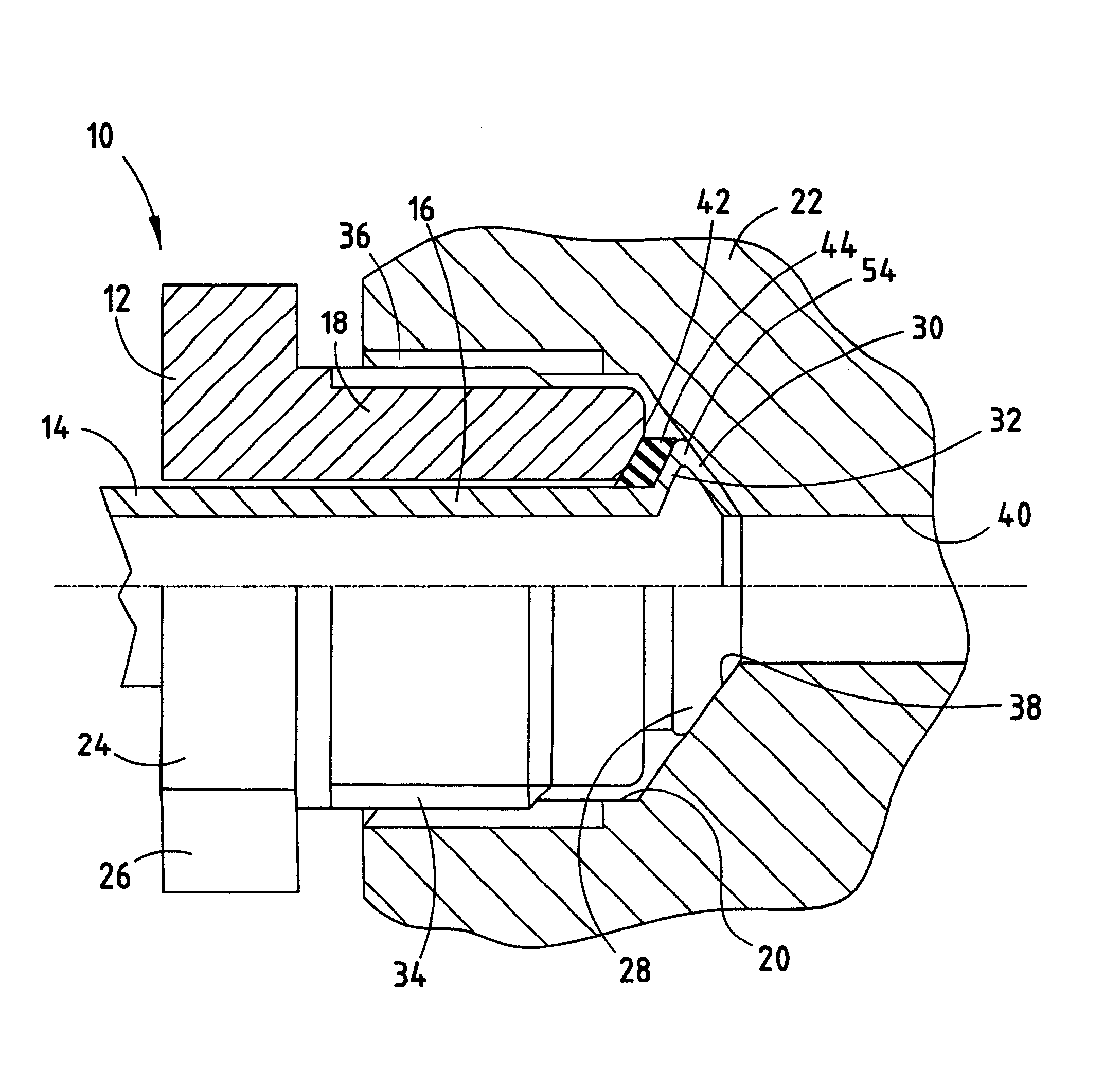
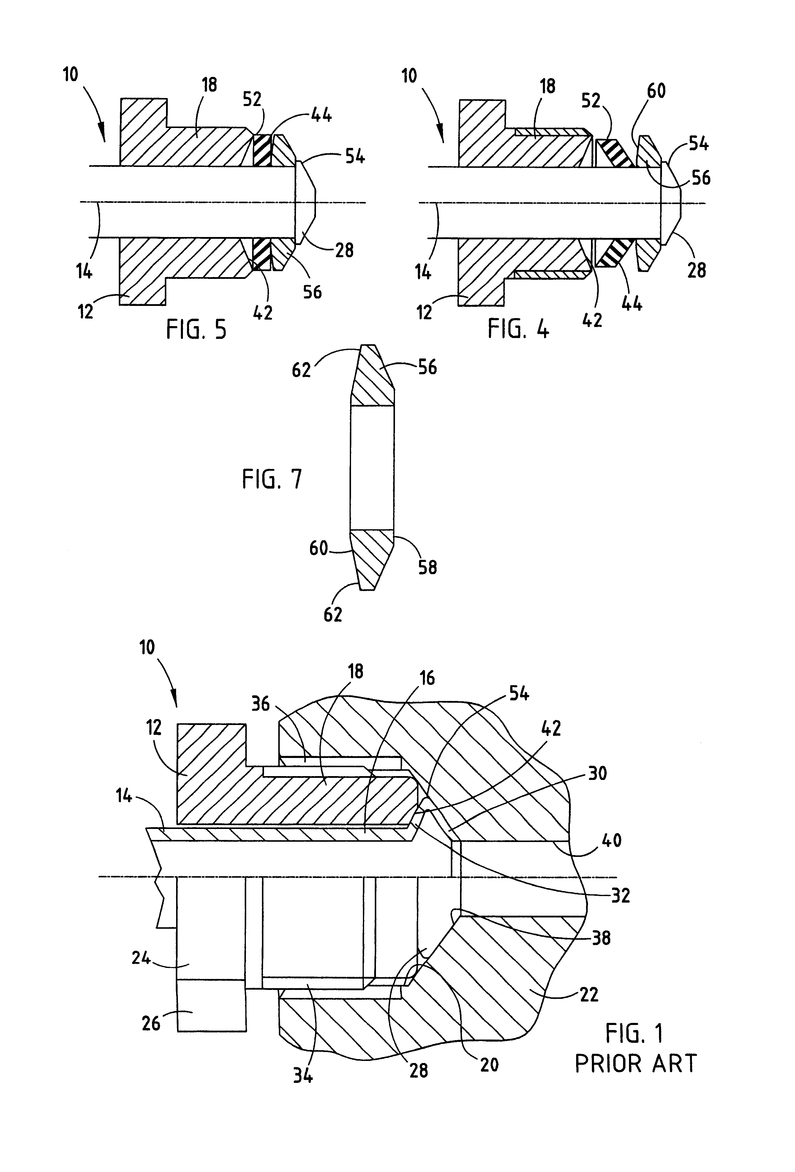
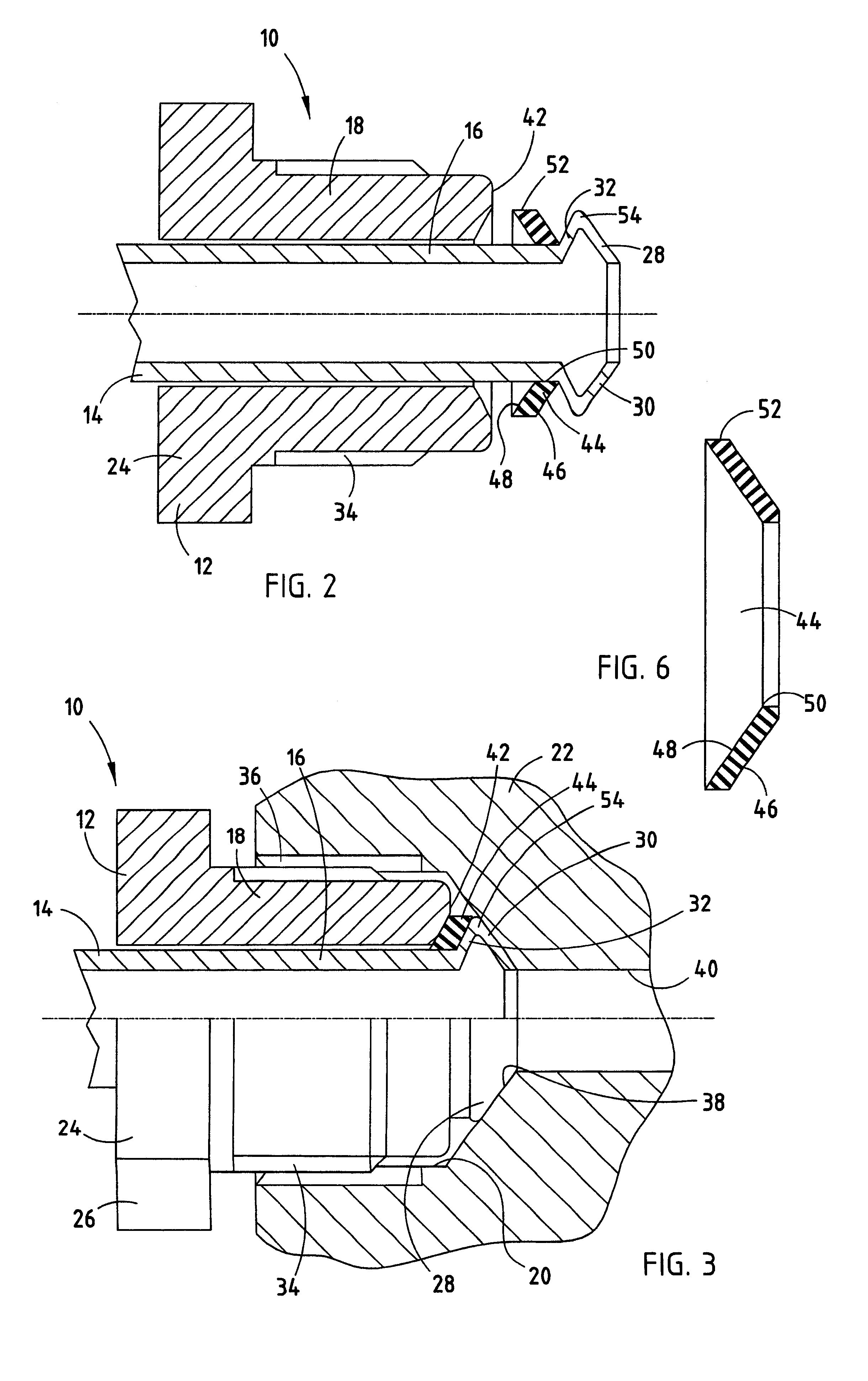
The best mode for carrying out the invention is resented in terms of the preferred embodiment, wherein similar reference characters designate corresponding features throughout the figures of the drawings. Referring now to the drawings, particularly FIG. 1, there is shown a connector 10 of the prior art used to seal an elongated tube to a body for flow of a fluid through said body. The connector 10 includes an elongated nut 12 that is disposed about a length of brake line or tube 14 near a proximate end 16 of the tube 14. As is conventional, the nut 12 has a threaded proximate end 18 that is adapted to engage a threaded hole 20 in the brake component 22. A distal end 24 of the nut 12 is provided with flats 26, as is conventional, for driving the nut 12 into the hole 20 to a specified torque by an air-driven gun. As shown, connector 10 of the prior art includes a flare 28 at the proximate end 16 of the tube 14. The flare 28, as is known, is provided with an interior face 30 and an ext...


PUM


Abstract

A connector (10) for sealing an elongated tube (14) to a body (22) comprises a nut (12) concentrically about the tube (14) proximate the flared end (16). The nut (12) has a threaded exterior portion (34) and an abutting face (42) proximate to and concentric with the exterior face (32) of the flared end (16). A non-linear spring (44) between the exterior face (32) of the flared end (16) and the abutting face(42) of the nut (12), and is displaced upon tightening of the nut (12) to the body (22) to generate a substantially constant restorative force over a portion of the displacement to urge the interior face (30) of the flared end (16) into sealing engagement with and against the shoulder (38) of the body (22).

Description

This invention relates to a high pressure fitting for a closed hydraulic fluid system of the type used in a motor vehicle to actuate the braking system. More particularly, the present invention relates to a threaded connector for a braking system that maintains a fluid-tight seal if the threaded connector becomes loose after assembly and in operation.DESCRIPTION OF THE RELATED ARTHigh pressure hydraulic fluid systems are commonly used in motor vehicle braking systems. A supply of hydraulic braking fluid is maintained in a master cylinder and, upon actuation of the brake pedal, supplied at elevated pressure (i.e., 2000 psi) to individual wheel cylinders. The wheel cylinders, in turn, urge friction surfaces into contact to generate a braking force. Thus, several component interfaces exist in motor vehicle braking systems that must maintain a relatively high brake fluid hydraulic pressure throughout the service life of the braking system. In light of the importance of motor vehicle bra...

Claims


Application Information

Patent Timeline
Patent Type & Authority Patents(United States)
IPC IPC(8): F16L19/02F16L19/025
CPCF16L19/025F16L19/0283B60T17/043
Inventor PLIASSOUNOV, STANISLAV IVANOVITCH
Owner FORD GLOBAL TECH LLC
Why Eureka
Try Eureka