Dechucking method and apparatus for workpieces in vacuum processors

a vacuum processor and workpiece technology, applied in the field of vacuum plasma processors, can solve problems such as the problem of removing certain workpieces from electrostatic chucks, and achieve the effects of increasing wafer throughput, effective measurement and control, and facilitating the removal of workpieces

Inactive Publication Date: 2005-02-17
LAM RES CORP
View PDF28 Cites 27 Cited by
  • Summary
  • Abstract
  • Description
  • Claims
  • Application Information

AI Technical Summary

Benefits of technology

is to provide a new and improved method of and apparatus for effectively measuring and controlling the forces applied to a workpiece by an electrostatic chuck...

Problems solved by technology

Removing certain workpieces from electrostatic chucks is a problem, particularly for semiconductor workpieces, as well as low and intermediate resistivity dielectric workpieces, (i.e., dielectric workpieces with resistivities less tha...

Method used


Image

  • Dechucking method and apparatus for workpieces in vacuum processors
  • Dechucking method and apparatus for workpieces in vacuum processors
  • Dechucking method and apparatus for workpieces in vacuum processors

Examples


second embodiment

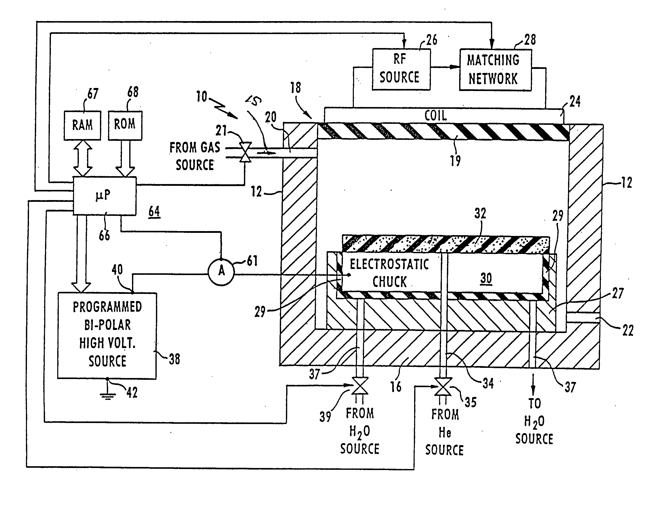
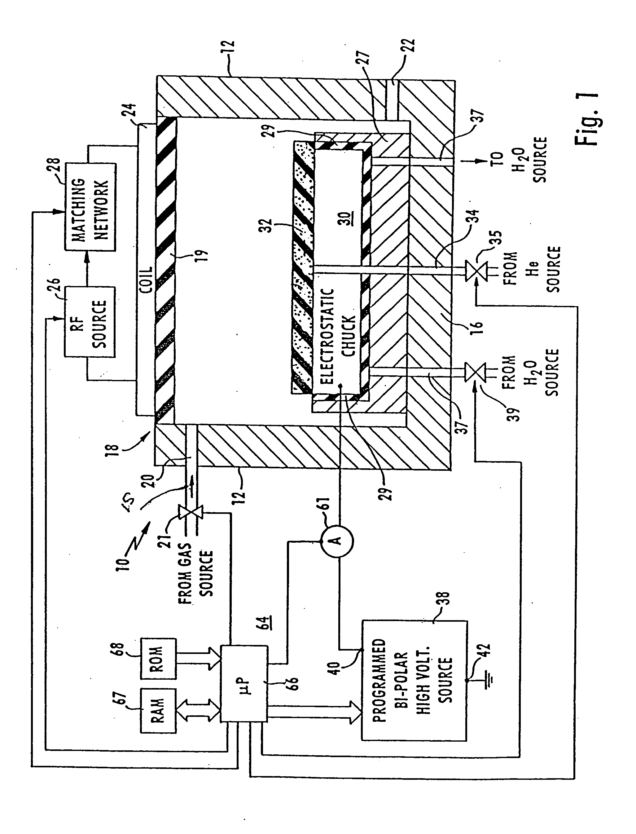
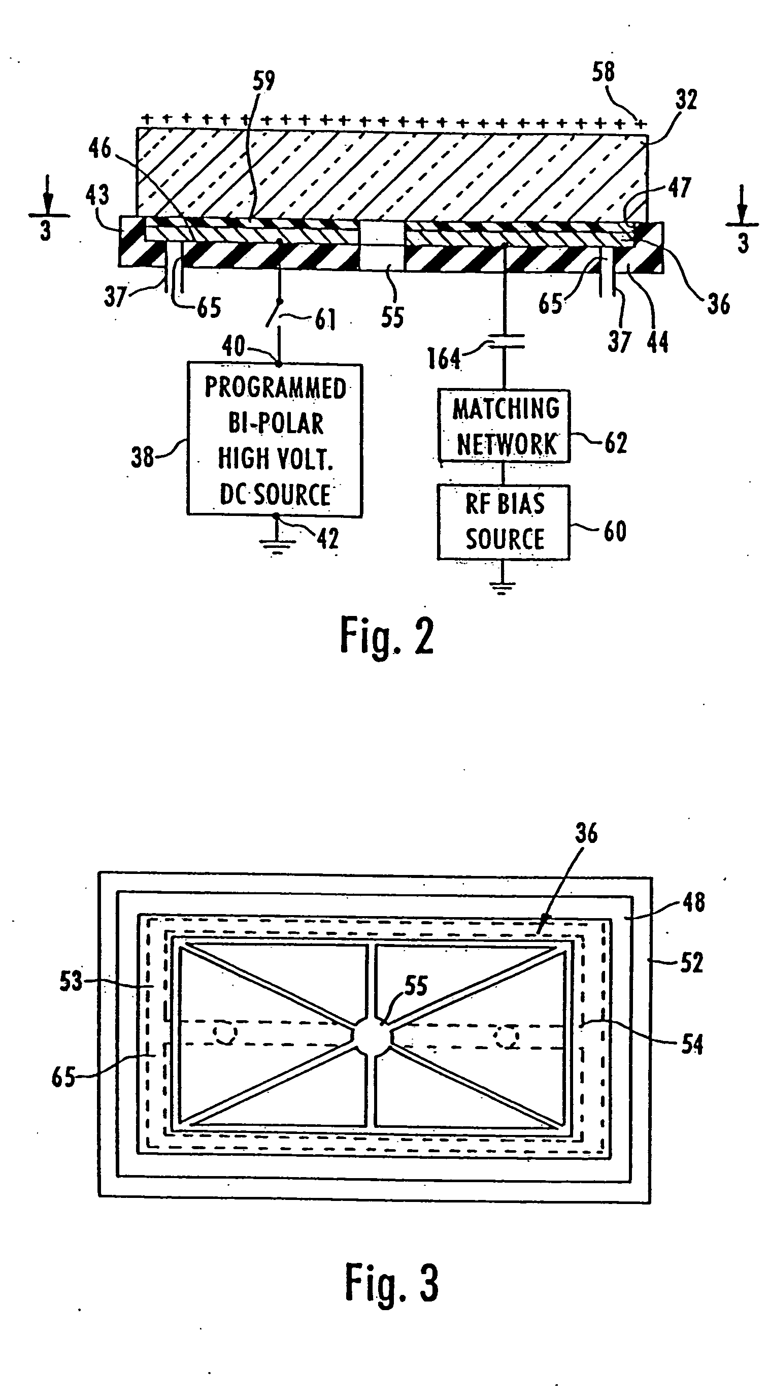
In accordance with a second embodiment, the amplitude of the reverse polarity voltage supplied by source 38 to terminal 40 is predetermined at a relatively high value, such as +4000 volts; the +4000 volt value is applicable to a situation wherein the voltages of source 36 are sequentially −1500V, −800V, −600V and −500V during processing. The reverse polarity voltage magnitude is selected to be such that VA (the voltage between the top face of electrode 36 and the bottom face of glass workpiece 32) is zero, which causes a substantial increase in VG (the voltage between the top and bottom faces of glass workpiece 32).

The magnitude of the reverse polarity voltage must be sufficient to attain this result, bearing in mind that the relative impedances of insulator 59 and glass workpiece 32 are such that only 5% to 10% of the voltage of source 38 is developed across capacitor CA. This dechucking method is for cases when the regular dechucking time constant τ− is very long. The very long t...

first embodiment

In the first embodiment, the reading of meter 61 controls the amplitude of the reverse polarity voltage and / or the length of time the reverse polarity voltage is applied by source 38 to chuck 30. Ideally, no current flows if the substrate was perfectly dechucked. If the most recent peak current increases in amplitude relative to the immediately preceding peak current, microprocessor 66 increases the amplitude of the applied reverse voltage and / or the length of time the reverse voltage is applied. If, however, the most recent peak current is negative in amplitude relative to the immediately preceding peak current, microprocessor 66 decreases the amplitude of the applied reverse polarity voltage and / or the length of time the reverse polarity voltage is applied to chuck 30.

The electrical resistivity of low and intermediate resistivity dielectric glass workpieces strongly depends on workpiece temperature as shown by Table I (supra). FIG. 6 is a plot of the discharge time constant τ− fo...


PUM

PropertyMeasurementUnit
Gamut indexaaaaaaaaaa
Forceaaaaaaaaaa
Electric potential / voltageaaaaaaaaaa

Abstract

A glass workpiece being processed in a vacuum plasma processing chamber is dechucked from a monopolar electrostatic chuck by gradually reducing the chucking voltage during processing while maintaining the voltage high enough to clamp the workpiece. A reverse polarity voltage applied to the chuck at the end of processing assists in dechucking. The workpiece temperature is maintained at a high value at the end of processing to assisting in dechucking. Peak current flowing through the chuck during lifting of the workpiece from the chuck controls the amplitude and/or duration of the reverse polarity voltage during the next dechucking operation.

Description

FIELD OF INVENTION The present invention relates generally to vacuum plasma processors including a chuck for holding workpieces in place during processing and, more particularly, to a method of and apparatus for facilitating dechucking wherein the force applied by the chuck to hold the workpiece in place during processing is effectively monitored and controlled. Another aspect of the invention relates to such processors wherein a voltage applied to an electrostatic chuck is controlled in response to current flowing between the chuck and a source of the voltage in response to current flowing through the chuck when a previously processed workpiece was removed from the chuck. BACKGROUND ART Vacuum plasma processors include a vacuum chamber containing a workpiece holder, i.e., chuck, for carrying a workpiece having an exposed surface which is plasma processed, i.e., a surface which a plasma etches and / or on which a plasma deposits materials. The etching and depositing are achieved in...

Claims


Application Information

Patent Timeline
IPC IPC(8): H01L21/00C23C16/458H01L21/302H01L21/3065H01L21/31H01L21/683H02N13/00
CPCH01L21/67242H02N13/00H01L21/6833H01L21/6831
Inventor HOWALD, ARTHUR M.HOLLAND, JOHN P.
Owner LAM RES CORP
Why Eureka
Try Eureka