Integrated thermal unit having a shuttle with a temperature controlled surface

a temperature controlled surface and integrated thermal unit technology, applied in electrical devices, thin material processing, ohmic resistance heating, etc., can solve the problems of direct affecting process variability and ultimately device performance, and achieve the effect of uniform thermal history, rapid reduction of a set point temperature of a bake plate, and minimizing the delay associated

Active Publication Date: 2006-10-26
SCREEN SEMICON SOLUTIONS CO LTD
View PDF8 Cites 6 Cited by
  • Summary
  • Abstract
  • Description
  • Claims
  • Application Information

AI Technical Summary

Benefits of technology

[0019] According to still another embodiment of the invention a method of rapidly reducing a set point temperature of a bake plate is provided. This embodiment comprises, after using the bake plate to heat a substrate disposed on an upper surface of the bake plate while the bake plate is in a baking position, vertically moving the bake plate to a lower position in which a lower surface of the bake plate contacts a plurality of heat sinks adapted to be engageably coupled to the lower surface of the bake plate.
[0020] Many benefits are achieved by way of the present invention over conventional techniques. For example, including bake and chill plates in one integrated unit minimizes the delay associated with transferring a baked wafer to the chill plate. Also, the inclusion of a shuttle having a temperature controlled substrate holding surface that transfers wafers between the bake and chill plates provides an additional degree of control over each wafer's thermal history thus enabling a more uniform thermal history among multiple wafers. Moreover, embodiments of the invention increase chamber throughput by decreasing the load on the main, central robot(s) of a track lithography tool and provide a safe haven for post-bake wafers in case of a malfunction of a main, central robot. Other embodiments increase wafer throughput by decreasing the amount of time it take to change the set point temperature of a bake plate from a first temperature to a second temperature lower than the first temperature. Depending upon the embodiment, one or more of these benefits, as well as other benefits, may be achieved. These and other benefits will be described in more detail throughout the present specification and more particularly below in conjunction with the following drawings.

Problems solved by technology

Lithography type device fabrication processes can be especially sensitive to variations in process recipe variables and the timing between the recipe steps, which directly affects process variability and ultimately device performance.

Method used


Image

  • Integrated thermal unit having a shuttle with a temperature controlled surface
  • Integrated thermal unit having a shuttle with a temperature controlled surface
  • Integrated thermal unit having a shuttle with a temperature controlled surface

Examples


Embodiment Construction

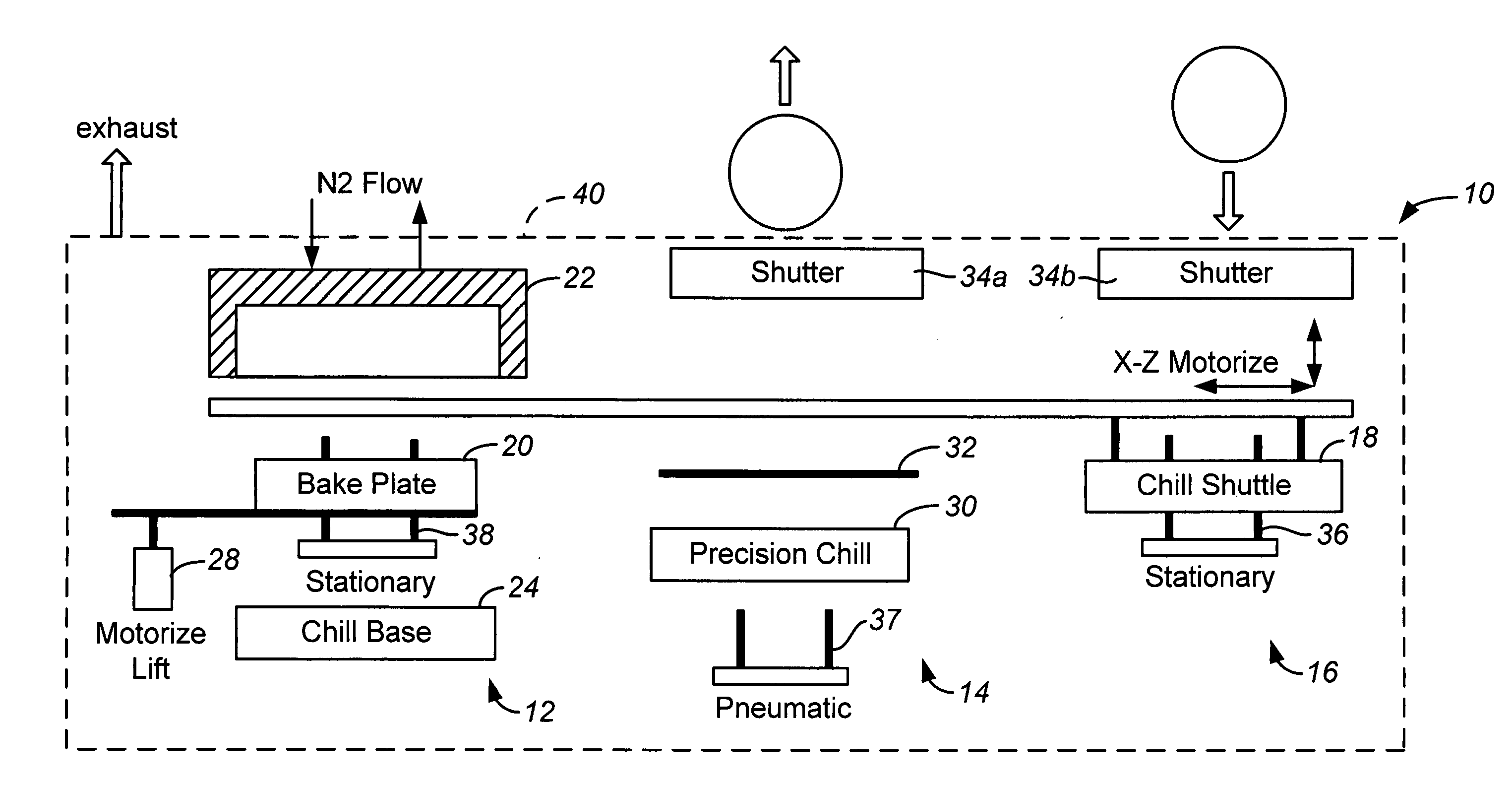
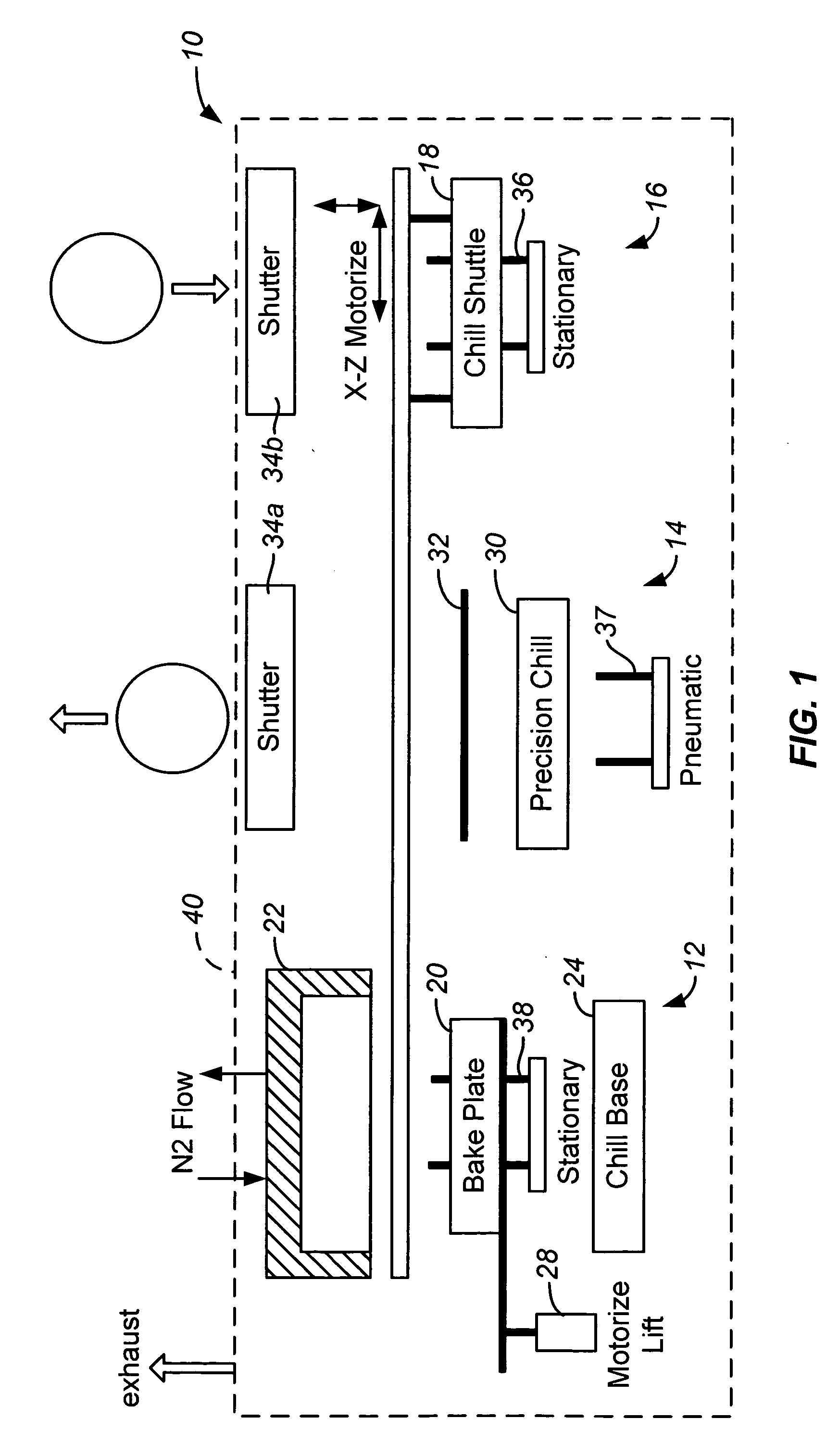
[0037] The present invention generally provides a method and apparatus for heating and cooling substrates in a highly controllable manner. While it is to be recognized that embodiments of the invention are particularly useful in helping to ensure a consistent wafer history for each substrate in a plurality of substrates that are heated and cooled according a particular thermal recipe within a track lithography tool, other embodiments of the invention can be used in other applications where it is desirable to heat and cool substrates in a highly controllable manner.

[0038]FIG. 1 is a simplified conceptual view of one embodiment of an integrated thermal unit 10 according to the present invention. Integrated thermal unit 10 includes a bake station 12, a chill station 14 and a shuttle station 16 all within an enclosed housing 40. Chill station 16 includes a shuttle 18 for transferring substrates between the bake and chill stations as needed. Bake station 12 includes a bake plate 20, an ...


PUM


Abstract

An integrated thermal unit comprising a bake plate configured to heat a substrate supported on a surface of the bake plate; a chill plate configured to cool a substrate supported on a surface of the chill plate; and a substrate transfer shuttle configured to transfer substrates from the bake plate to the cool plate, wherein the substrate transfer shuttle has a temperature controlled substrate holding surface that is capable of cooling a substrate heated by the bake plate.

Description

CROSS-REFERENCES TO RELATED APPLICATIONS [0001] This application claims priority to U.S. Provisional Application No. 60 / 674,018, filed Apr. 21, 2005, the disclosure of which is hereby incorporated by reference in its entirety.[0002] This application is related to U.S. Application No. ______, filed ______ (Attorney Docket No. A9999.2 / T60620); and to U.S. Application No. ______, filed ______ (Attorney Docket No. A9999.3 / T60630); and to U.S. Application No. ______, filed ______ (Attorney Docket No. A9999.4 / T60900). Each of the applications listed above are assigned to Applied Materials, Inc., the assignee of the present invention and are hereby incorporated by reference. BACKGROUND OF THE INVENTION [0003] The present invention relates generally to the field of substrate processing equipment. More particularly, the present invention relates to a method and apparatus for controlling the temperature of substrates, such as semiconductor substrates, used in the formation of integrated circu...

Claims


Application Information

Patent Timeline
Patent Type & Authority Applications(United States)
IPC IPC(8): H05B3/68
CPCH01L21/67109Y10S414/135H01L21/67742H01L21/67184
Inventor QUACH, DAVID H.SALINAS, MARTIN JEFF
Owner SCREEN SEMICON SOLUTIONS CO LTD
Why Eureka
Try Eureka