Exercise apparatus using weights and springs for high-speed training

a technology of exercise apparatus and springs, applied in the field of exercise equipment, can solve the problems of uncontrollable and sometimes dangerous variation in the force applied to the handle, damage to the user, and equipment not maintaining this constant gravitational force, so as to avoid undue friction

Inactive Publication Date: 2006-05-18
BVP HLDG
View PDF62 Cites 29 Cited by
  • Summary
  • Abstract
  • Description
  • Claims
  • Application Information

AI Technical Summary

Benefits of technology

[0017] In another embodiment of the invention, the spring device may comprise one or more compression springs which are connected between the top most weight and the top frame of the exercise apparatus. In this case, the springs may be applied to press against the top most weight with a balanced force, to avoid causing undue frictio

Problems solved by technology

However, such equipment does not maintain this constant gravitational force when the handle is moved rapidly back and forth by the user—an exercise known as “high-speed training”.
In this case, the momentum developed by the weight during the high-speed movement creates an uncontrollable and sometimes dangerous variation in the force applied to the handle.
In the case of machines with a pivoted traveling arm, the variation in gravitational force may be so great, as the arm switches directions, that it can be harmful to the user as he or she braces to try and hold on to the handle.
Similarly, with machines which employ a cable connected to a weight, the weight can be caused to fly up along the guide rods, causing the tension in the cable to fall to zero, and then “bounce back” with a sudden jerk of the cable and a consequent spike in the cable tension, as the weight falls back down again and the cable brakes its descent.
However, with high-speed training movements, the force due to weights varies considerably.
As compared to an exercise machine wh

Method used


Image

  • Exercise apparatus using weights and springs for high-speed training
  • Exercise apparatus using weights and springs for high-speed training
  • Exercise apparatus using weights and springs for high-speed training

Examples


Embodiment Construction

[0038] The preferred embodiments of the present invention will now be described with reference to FIGS. 1-15 of the drawings. Identical elements in the various figures are designated with the same reference numerals.

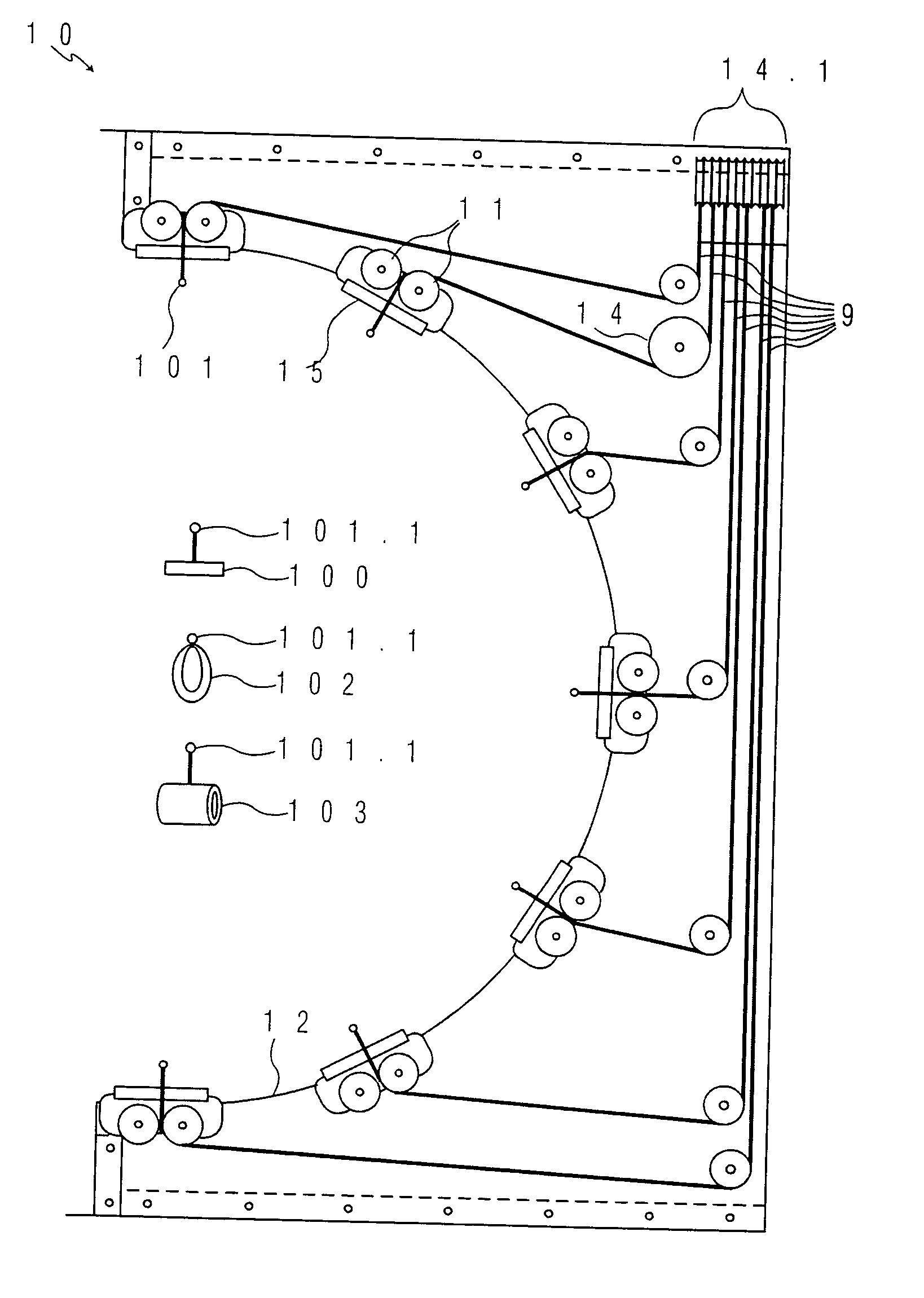
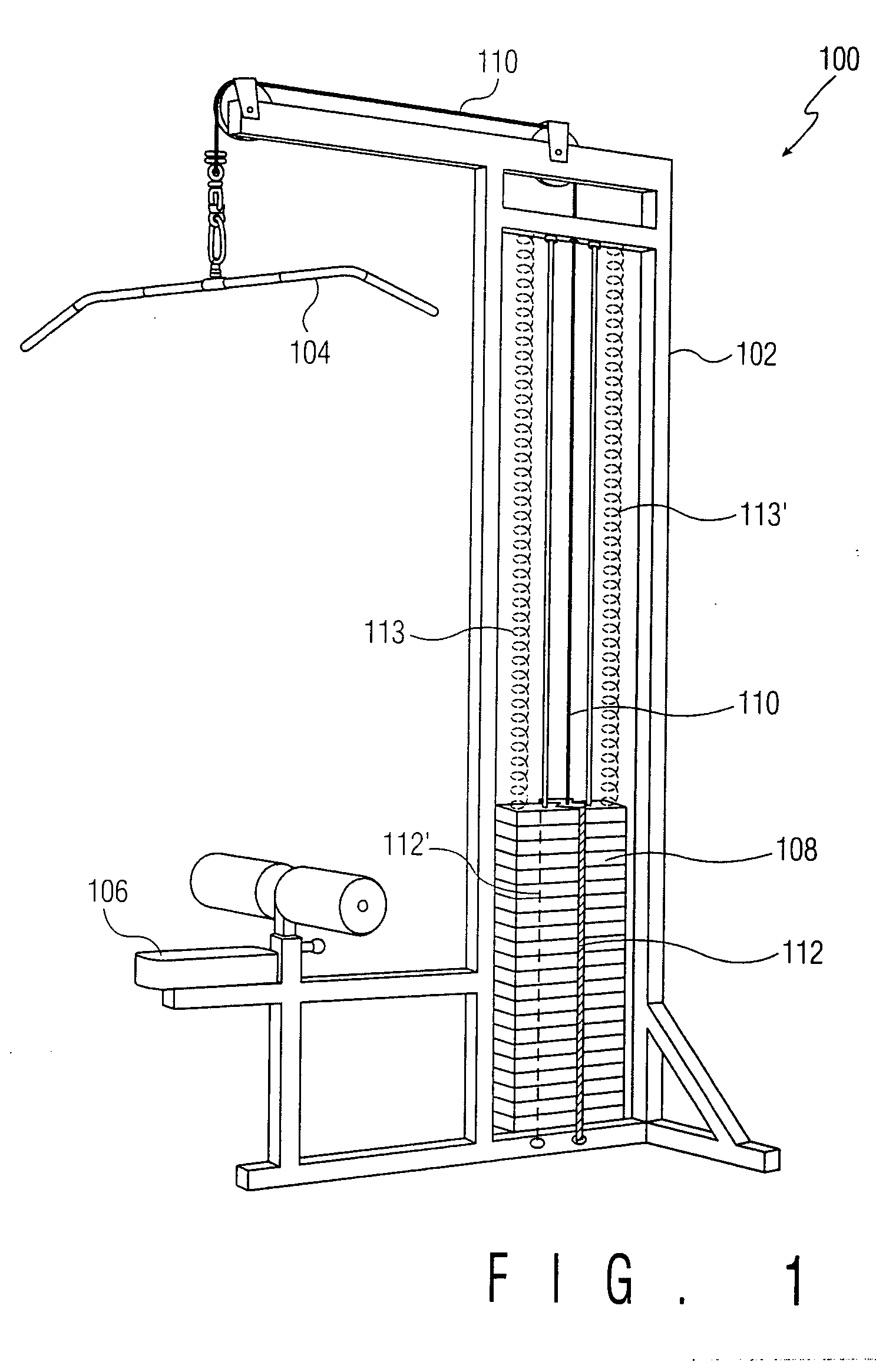
[0039]FIG. 1 shows an exercise machine 100 having a frame structure 102; a handle 104 adapted to be gripped by a user, who may either stand or be seated on a seat 106; and a cable 110 which couples the handle to a stack of weights 108. The number of weights in the stack 108 may be selected by the user to vary the gravitational force applied to the cable 110 and, thus, to the handle 104. As the handle 104 is pulled slowly by a user, one or more of the weights 108 at the top of the stack are lifted and thus supply substantially constant tension to the cable 110.

[0040] According to the invention, a spring device 112, which may be an elastic (e.g., rubber) band, a coil spring, bungee cord or the like, is connected between the top of the weight stack 108 and the frame 102 o...


PUM


Abstract

Exercise equipment of the type comprising a frame structure; a handle coupled to the frame structure and adapted for movement by a user, back and forth in a first direction and in an opposite second direction; and at least one weight, coupled to the handle for applying a gravitational force to the handle in the second direction. According to the invention, a spring device, having two ends, is coupled to the handle at one end and to the frame structure at the opposite end to apply a spring force to the handle in the second direction. With proper choice of the spring constant of the spring device, when the handle is rapidly moved by the user in the first direction and then suddenly moved in the second direction, the total force applied to the handle in the second direction is maintained above minimum threshold value which is sufficient for “high-speed training”.

Description

CROSS REFERENCE TO RELATED APPLICATION [0001] This present application claims benefit of priority from U.S. patent application Ser. No. 09 / 678,931, filed Oct. 4, 2000, entitled “EXERCISE APPARATUS”, now U.S. Pat. No. 6,705,976; U.S. patent application Ser. No. 09 / 965,032, filed Sep. 27, 2001, entitled “WEIGHT SYSTEMS FOR EXERCISE EQUIPMENT”; and U.S. patent application Ser. No. 10 / 736,807, filed Dec. 15, 2003, entitled “EXERCISE APPARATUS USING WEIGHTS FOR HIGH-SPEED TRAINING”.BACKGROUND OF THE INVENTION [0002] The present invention relates to exercise equipment of the type which utilizes one or more weights to apply a force to a movable handle. [0003] Various types of exercise equipment are known wherein one or more weights are used to exert a gravitational force against a handle or the like which is moved by a user. For example, in one type of device, the handle is attached to one end of a pivot arm that allows the handle to be moved up or down by a user. A weight is either attach...

Claims


Application Information

Patent Timeline
IPC IPC(8): A63B21/06A63B21/062
CPCA63B21/00065A63B21/0428A63B21/055A63B21/0552A63B21/0615A63B21/062A63B21/1469A63B21/1484A63B21/1492A63B21/154A63B21/156A63B21/159A63B23/12A63B2208/0228A63B21/0628A63B21/4035A63B21/4043A63B21/4047A63B23/03525A63B23/03533A63B23/03541A63B23/1209
Inventor PIANE, ROBERT A. JR.
Owner BVP HLDG
Why Eureka
Try Eureka