Double-vane hydraulic self-servo oscillating cylinder

A self-servo, swing cylinder technology, applied in the field of double-blade hydraulic self-servo swing cylinder, can solve the problems of complex structure, small flow, poor dynamic characteristics of the valve core, etc., and achieve the effect of simple oil channel structure, simple structure and convenient processing.

Active Publication Date: 2013-05-22
武汉科技大学资产经营有限公司
View PDF7 Cites 10 Cited by
  • Summary
  • Abstract
  • Description
  • Claims
  • Application Information

AI Technical Summary

Problems solved by technology

The servo valve also has the difficulty of preparing the hidden oil passage inside the servo valve sleeve, the valve core has poor dynamic characteristics, and the radial dimension is large.
[0005] Jiang Lin, a scholar of Wuhan University of Science and Technology, etc., also has a complex structure in the patented technology of "An Easy-to-Control Hydraulic Angle Self-servo Valve" (CN 201210033081.6). There are many complicated inner oil passages inside the sleeve, it is difficult to ensure the machining accuracy, the flow rate is small, the flow gain is non-linear, and the radial dimension is large
[0006] In addition, Jiang Lin, a scholar of Wuhan University of Science and Technology, also designed "a rotary valve type high torque hydraulic angle self-servo valve" (CN201210514025.4), the servo valve Although the radial force of the spool has been balanced and the resistance of the spool has been relatively reduced, there is also a complex structure. The spool and the valve sleeve are radially matched, and the position of the spool and the valve sleeve must be assembled radially. The radial dimension of the vane is reduced, resulting in a larger radial dimension of the servo valve

Method used


Image

  • Double-vane hydraulic self-servo oscillating cylinder
  • Double-vane hydraulic self-servo oscillating cylinder
  • Double-vane hydraulic self-servo oscillating cylinder

Examples


Embodiment 1

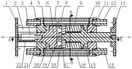
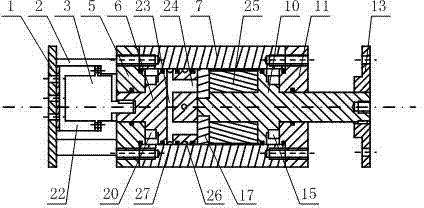
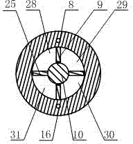
[0041]A double vane hydraulic self-servo swing cylinder. The double vane hydraulic self-servo swing cylinder as figure 1 and figure 2 As shown, it includes a motor 3, a cylinder body 7, a valve body 6, a swing output shaft 10, a flow plate 17, a fixed block 9, a vane 25, a left end cover 5 and a right end cover 11.

[0042] Such as figure 1 and figure 2 As shown, the left end of cylinder block 7 is equipped with left end cover 5, and left bearing 20 is housed in cylinder block 7, and left bearing 20 is close to the inner side of left end cover 5, and the stepped shaft on the left side of valve body 6 passes through left bearing 20 and left end cover 5 The center hole of the valve body is installed in the cylinder body 7, the left end of the valve body 6 is fixedly connected with the output shaft of the motor 3, the motor 3 is fixedly connected with the left flange 1 through the bracket plate 22, and the left flange 1 is connected with the left end through the bracket rod ...

Embodiment 2

[0055] A double vane hydraulic self-servo swing cylinder. Except following situation, all the other are with embodiment 1.

[0056] When the double-blade hydraulic self-servo swing cylinder adopts multi-stage series connection, the plug 14 installed at the outlet of the high-pressure oil passage of the right end cover 11 is replaced with a high-pressure oil outlet pipe joint 14, and the high-pressure oil outlet pipe joint 14 passes through the pipeline and the lower The high-pressure oil inlet pipe joint 21 of the first stage is connected; the plug 12 installed at the inlet of the low-pressure oil passage of the right end cover 11 is replaced with the low-pressure oil inlet pipe joint 12, and the low-pressure oil inlet pipe joint 14 is connected to the low-pressure oil outlet pipe of the next stage through the pipeline. Connector 4 is connected. A plug 14 is installed at the high-pressure oil passage outlet of the right end cover 11 of the last-stage double-blade hydraulic se...


PUM


Abstract

The invention relates to a double-vane hydraulic self-servo oscillating cylinder. According to the technical scheme, two fixed stoppers (9) are symmetrically fixed on the inner wall of a cylinder body (7). Two vanes (25) are symmetrically fixed on an oscillating output shaft (10). The two vanes (25) and the two fixed stoppers (9) are in staggered arrangement. The valve body (6) and the oil distribution disc (17) are used for oil distribution for end faces. High-pressure oil enters two corresponding work cavities through a high-pressure oil way (16), a radial high-pressure oil way of the cylinder (7), a high-pressure annular oil groove (27) and a high-pressure radial oil passage (23) and a high-pressure radial oil passage (19). Low-pressure oil of the other two work cavities returns through a low-pressure oil distribution oil way (18), a low-pressure radial oil passage (19), a low-pressure annular oil groove (26), a radial low-pressure oil way of the cylinder body (7) and a low-pressure oil way (8). The double-vane hydraulic self-servo oscillating cylinder is small in radial size, good in dynamic property, simple in oil ways, convenient to machine and easy to produce, and stress of the valve body (6) and the oscillating output shaft (10) is balanced.

Description

technical field [0001] The invention belongs to the technical field of hydraulic servo swing cylinders, in particular to a double-blade hydraulic self-servo swing cylinder. Background technique [0002] The double-vane hydraulic self-servo swing cylinder can convert the small power input by the motor into the high power output by the hydraulic pressure, so as to control the equipment with high torque and precise rotation angle. [0003] At present, Professor Zhu Xinglong of Yangzhou University in China has studied a hydraulic servo joint (Zhu Xinglong et al. Research on Dynamics Modeling and Simulation of 3-DOF Hydraulic Servo Joint. Mechanical Design and Manufacturing Engineering, 2002,31(6):23-25. ) technology, because there is only a pair of oil ports on the rotary valve core of this hydraulic servo joint, the radial force on the valve core is unbalanced due to structural reasons, and at the same time, one end of the valve core is easy to form a dead space, and the dynami...

Claims


Application Information

Patent Timeline
Patent Type & Authority Applications(China)
IPC IPC(8): F15B15/12F15B15/20
Inventor 蒋林张宏伟胡琪刘白雁梅鹏吴若麟晏晚君郑翠胡金郑开柳向贤宝曾镛金晓宏赵慧曾良才
Owner 武汉科技大学资产经营有限公司
Why Eureka
Try Eureka