
Corner self-servo passive and supple hydraulic robot joint

A hydraulic robot and self-servo technology, applied in manipulators, program-controlled manipulators, manufacturing tools, etc., can solve problems such as poor assembly of the valve body, difficult machining accuracy, and easy displacement of the valve body.

Active Publication Date: 2017-05-31
WUHAN UNIV OF SCI & TECH
View PDF6 Cites 10 Cited by
  • Summary
  • Abstract
  • Description
  • Claims
  • Application Information

AI Technical Summary

Problems solved by technology

[0003] "An easy-to-control hydraulic angle self-servo valve" (ZL 201210033081.6) patented servo valve spool has the advantages of easy preparation, balanced radial force and axial force on the spool, good dynamic characteristics, small servo blind zone and easy control characteristics, but the structure is complex, especially there are many complex inner oil passages inside the valve core and valve sleeve, it is difficult to guarantee the machining accuracy, and there is also the fact that the output torque is not large enough and the circular valve port design is used, resulting in its flow gain It is non-linear, which leads to the problem of insufficient precision
[0004] The patented technology of "A Rotary Valve Type Large Torque Hydraulic Rotary Angle Self-Servo Valve" (ZL 201210514025.4) overcomes the above-mentioned problems. The servo valve improves the flow capacity of the system and the response speed by distributing flow on the surface of the valve core. However, there are problems that the fixed block is not easy to fix, it is not easy to assemble, and the valve body is supported by a separate bearing, which causes the valve body to be easily displaced under force, increases the friction of the valve body, and affects flexibility.

Method used


Image

  • Corner self-servo passive and supple hydraulic robot joint
  • Corner self-servo passive and supple hydraulic robot joint
  • Corner self-servo passive and supple hydraulic robot joint

Examples


Embodiment Construction

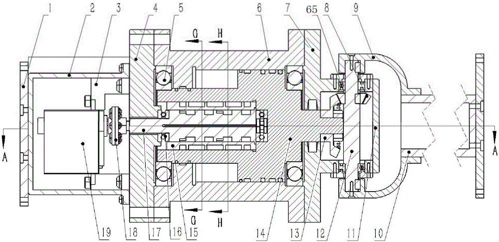
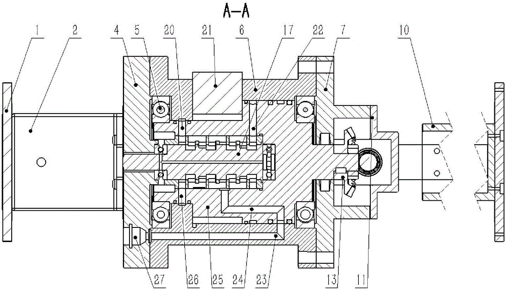
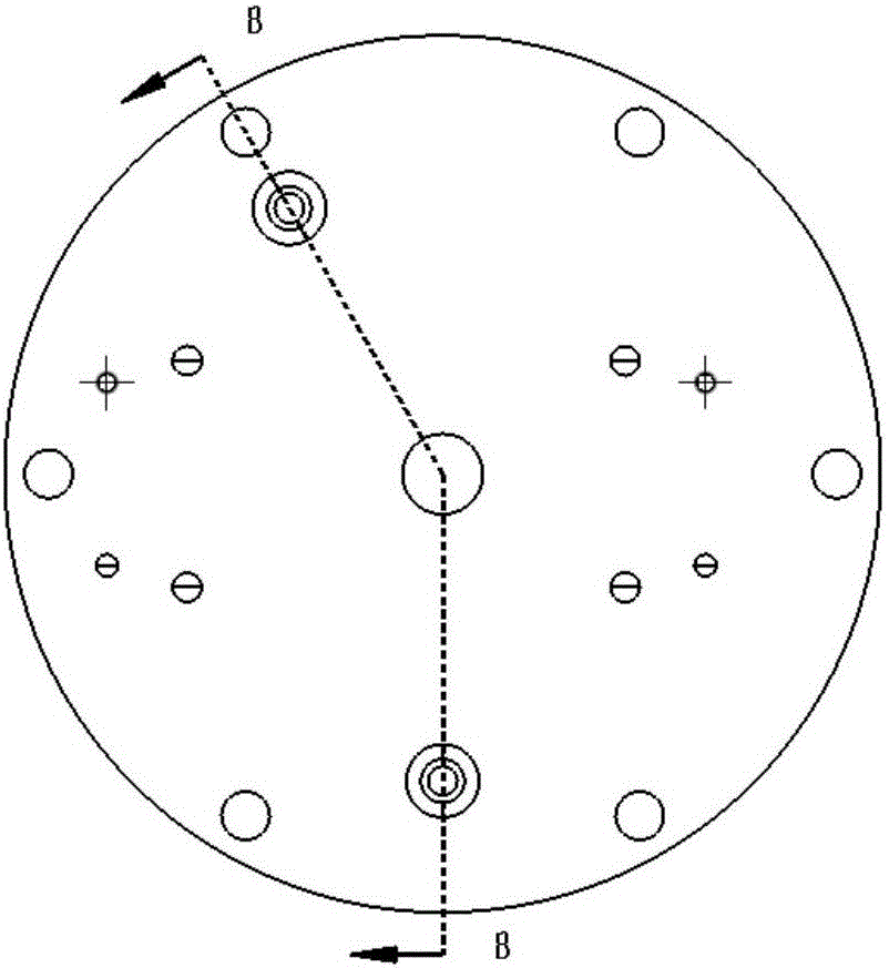
[0078] Below by embodiment, in conjunction with accompanying drawing, the technical scheme of the present invention is described further specifically, as Figure 1-26 As shown, a corner self-servo passive compliant hydraulic robot joint includes a steering gear 19, a steering gear cover 2, a steering gear disc 18, a steering gear seat 3, a cylinder body 6, a valve sleeve 15, a valve core 17, a valve body 14, Fixed block 21, blade 25, driving bevel gear 13, driven shaft 12, driven bevel gear 8, gear cover 11, connecting rod 9, driven arm 10 and connection plate 1;

[0079] Such as figure 1 and figure 2 As shown, the valve body 14 is concentrically installed in the cylindrical cavity 32 of the cylinder body, and the left and right ends of the valve body 14 are concentrically equipped with two deep groove ball bearings 5, and the left end deep groove ball bearing is fixed on the left bearing of the cylinder body. In the groove 29, the right end deep groove ball bearing is fixe...


PUM


Abstract

The invention provides a corner self-servo passive and supple hydraulic robot joint. According to the technical scheme of the corner self-servo passive and supple hydraulic robot joint, a valve body (14) is concentrically installed in a cylindrical cavity (32) of a cylinder body; the left end and the right end of the valve body (14) are concentrically provided with two deep groove ball bearings (5); a driving bevel gear (13) is concentrically installed on the shaft shoulder of an output shaft at the right end of the valve body (14); a driven shaft (12) is installed on a right end cover (7); a driven bevel gear (8) is concentrically installed on the driven shaft (12); two connecting rods (9) are fixedly and symmetrically installed at the two ends of the driven shaft (12) through screws; and a driven arm (10) is installed between the other ends of the two connecting rods (9). The corner self-servo passive and supple hydraulic robot joint has the beneficial effects that a fixing stop block can be fixed easily and assembled easily, the output torque of the joint is large, the force borne by the valve body is in balance, displacement is not prone to occurrence, the dynamic characteristic is good, the joint flexibility is good, the response speed is high, and the control precision is high.

Description

technical field [0001] The invention belongs to the technical field of robot joints, in particular to a passive and compliant hydraulic robot joint with corner self-servo. Background technique [0002] The hydraulic angle servo technology is a combination of hydraulic pressure and motor technology. Using their respective advantages, the small torque of the motor directly drives the valve core to open the valve port, allowing high-pressure oil to act on the valve body, thereby obtaining a large output torque. The hydraulic angle self-servo valve is the core component of the hydraulic control system. It has the characteristics of high precision and fast response. It is widely used in high-precision mechatronics systems, aerospace airborne drive systems, and large-scale test equipment. Therefore, Get the attention of scientific and technological personnel at home and abroad. [0003] "An easy-to-control hydraulic angle self-servo valve" (ZL 201210033081.6) The patented servo v...

Claims


Application Information

Patent Timeline
IPC IPC(8): B25J17/02B25J9/14
CPCB25J9/148B25J17/0208
Inventor 蒋林谢维王翰周亮于志鹏高旭敏王钊赵慧朱建阳田体先
Owner WUHAN UNIV OF SCI & TECH
Learn More