Orthopedic fixation device

Inactive Publication Date: 2006-01-05
AESCULAP AG
View PDF12 Cites 212 Cited by
  • Summary
  • Abstract
  • Description
  • Claims
  • Application Information

AI Technical Summary

Benefits of technology

[0007] With such a device, it is a simple matter to push the rod-like fixation element from above in between the two clamping jaws and then simply fix it by rotating the cam body. In this way, complicated screwing operations with a great many rotations are unnecessary, so that these procedures can also easily be performed through small openings in the body. Maneuvering of the cam body can additionally be made easier by the fact that the rotatability of the cam body is limited, for example by limit stops, in the tightening direction and / or in the release direction. On the one hand, this gives the operating surgeon an indication of whether a complete tightening or release of the cam body has taken place, and, on the other hand, this avoids overtightening, which could in some cases result in the device being damaged. This limiting action can be provided by limit stops.
[0031] A particularly simple configuration is obtained if the transverse support has an elongate hole in which the bone screw, the clamp piece and the cam are accommodated. By rotating the cam, the latter and the bone screw are pressed against the edge of the elongate hole and clamped.

Problems solved by technology

In this way, complicated screwing operations with a great many rotations are unnecessary, so that these procedures can also easily be performed through small openings in the body.

Method used


Image

  • Orthopedic fixation device
  • Orthopedic fixation device
  • Orthopedic fixation device

Examples


Embodiment Construction

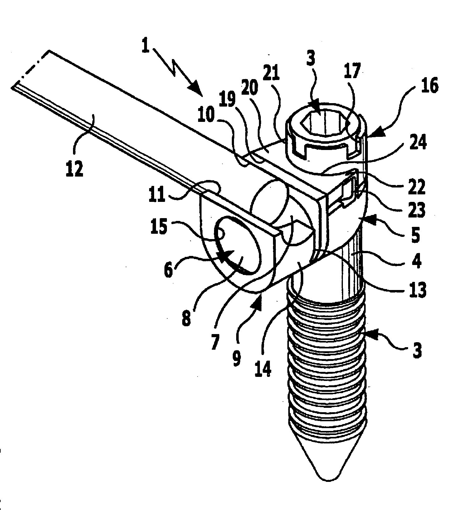
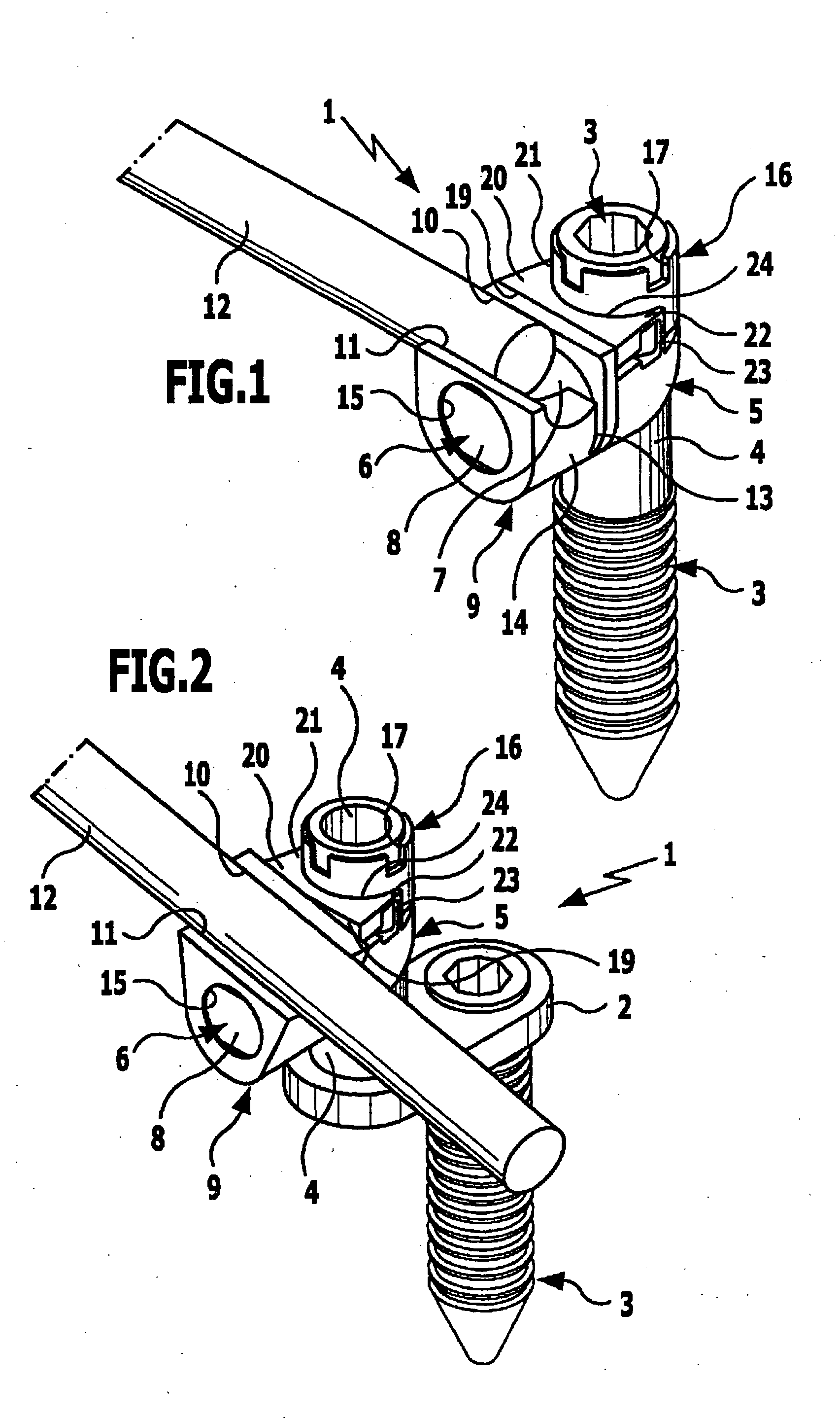
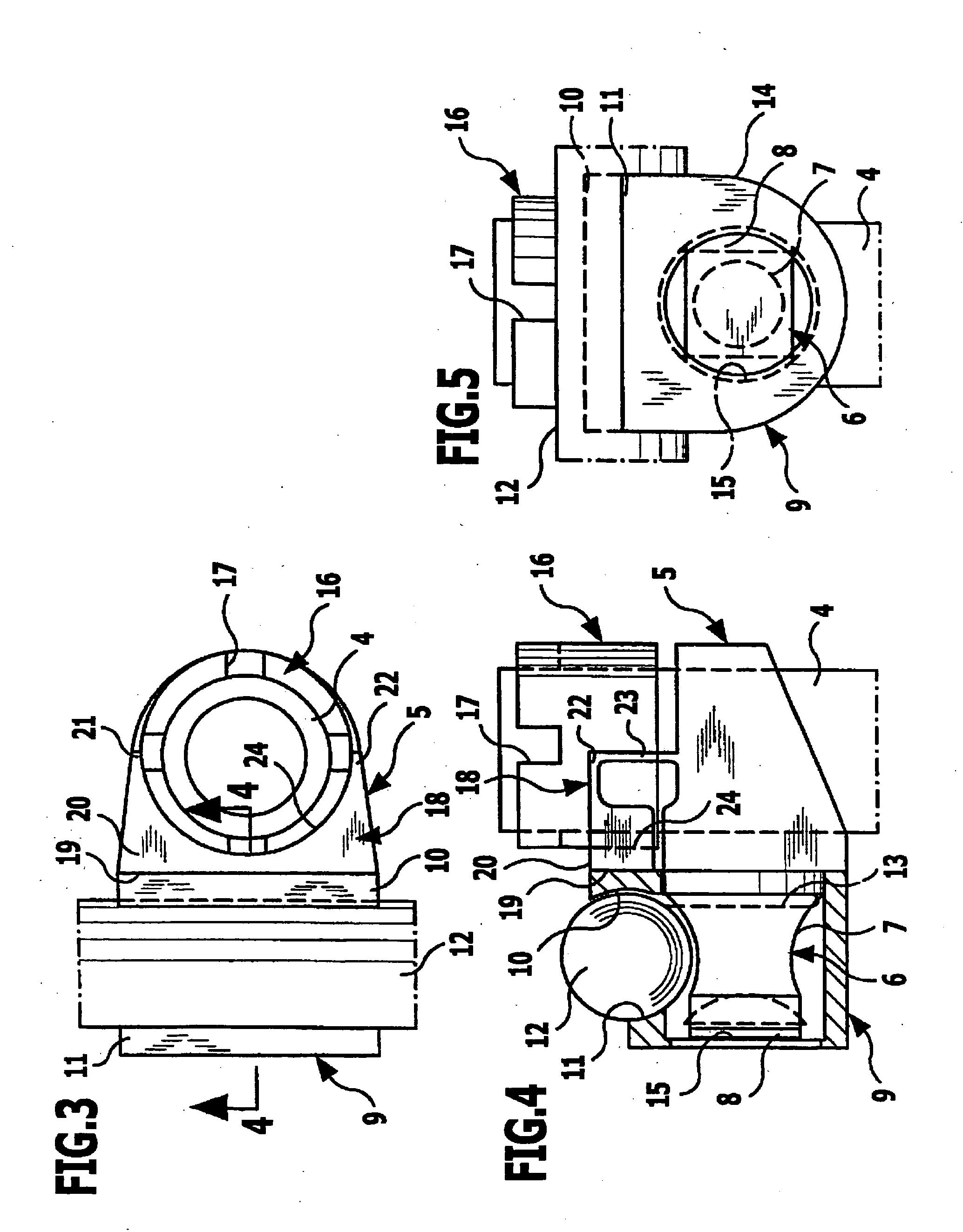
[0061] The orthopedic fixation device 1 shown in FIGS. 1 to 8 is, in the illustrative embodiment in FIG. 1, fitted onto the shaft of a bone screw 3 whereas, in the illustrative embodiment in FIG. 2, it is fitted onto a sleeve-shaped, cylindrical mounting body 4 which is disposed on the bone screw 3 in a laterally offset position by way of a transverse support 2. In the following description, both the shaft of the bone screw 3 and the cylindrical mounting body 4 of the transverse support 2 are referred to jointly as mounting body 4, although it will be appreciated that the described orthopedic fixation device 1 can be fitted onto a wide variety of pin-shaped, shaft-shaped or sleeve-shaped mounting bodies.

[0062] A support piece 5 is pushed onto the mounting body 4 from above, tightly surrounds the mounting body 4 and is freely rotatable thereon. This support piece 5 has a mounting shaft 6 which protrudes from it in a direction transverse to the longitudinal direction of the mounting ...


PUM


Abstract

The invention relates to an orthopedic fixation device for securing a rod-like fixation element, with two clamping jaws which can be moved relative to one another and which, when brought together, clamp the fixation element between them. In order to permit space-saving configurations of a fixation device that can be introduced and operated through small orifices in the body, a cam body is provided which is mounted on the fixation device so as to be able to rotate next to the clamping jaws in the direction of tightening and which, when rotated, pushes one clamping jaw toward the other.

Description

[0001] This application is a continuation of international application number PCT / EP2002 / 009878 filed on Sep. 4, 2002. [0002] The present disclosure relates to the subject matter disclosed in international application No. PCT / EP2002 / 09878 of Sep. 4, 2002, which is incorporated herein by reference in its entirety and for all purposes.BACKGROUND OF THE INVENTION [0003] The invention relates to an orthopedic fixation device for securing a rod-like fixation element, with two clamping jaws which can be moved relative to one another and which, when brought together, clamp the fixation element between them. [0004] To fix bones or bone parts relative to one another, for example in the region of the spinal column, it is known to use rod-like fixation elements which, at different locations, are clamped between clamping jaws, and these clamping jaws are then connected by bone screws or similar fixation means to the bones or bone fragments to be fixed (WO 97 / 06742; U.S. Pat. No. 5,741,255; U.S....

Claims


Application Information

Patent Timeline
Patent Type & Authority Applications(United States)
IPC IPC(8): A61B17/56A61B17/70
CPCA61B17/7041
Inventor KRAMER, ULRICHSCHUMACHER, JOERGPOTULSKI, MICHAELBEISSE, RUDOLFKOZAK, JEFFREY ALAN
Owner AESCULAP AG
Why Eureka
Try Eureka