Automatic elevating apparatus and method of aeration tube of floating aerator

An automatic lift and aerator technology, applied in chemical instruments and methods, water aeration, aerobic process treatment, etc., can solve the problems of poor effect and short oxygenation time, and achieve small water flow resistance, small cross-section, prolonged The effect of time of contact

Active Publication Date: 2017-02-22
沈晓笑
View PDF11 Cites 11 Cited by
  • Summary
  • Abstract
  • Description
  • Claims
  • Application Information

AI Technical Summary

Problems solved by technology

[0009] Aiming at the problems of short oxygenation time and poor effect in the aeration and oxygenation equipment in the prior art, the present invention provides an automatic lifting device and method for the aeration tube of the floating aerator

Method used


Image

  • Automatic elevating apparatus and method of aeration tube of floating aerator
  • Automatic elevating apparatus and method of aeration tube of floating aerator
  • Automatic elevating apparatus and method of aeration tube of floating aerator

Examples


Embodiment 1

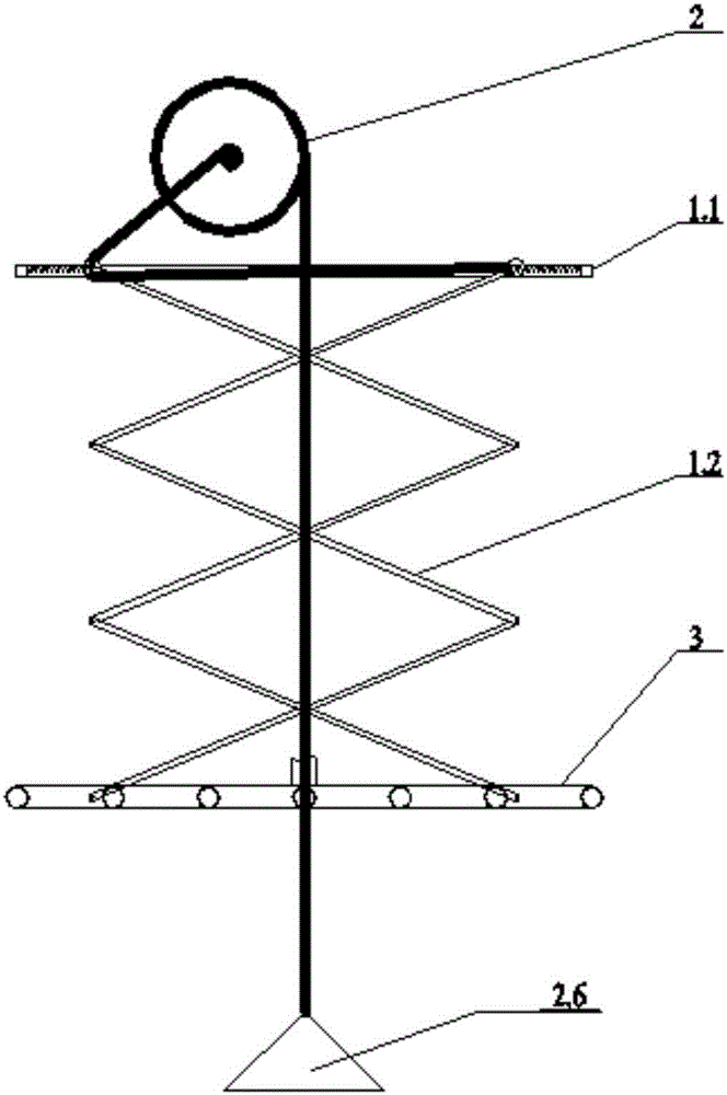
[0062] When it is placed in the river for the first time, the robotic arm 1.2 automatically adapts and stretches out.

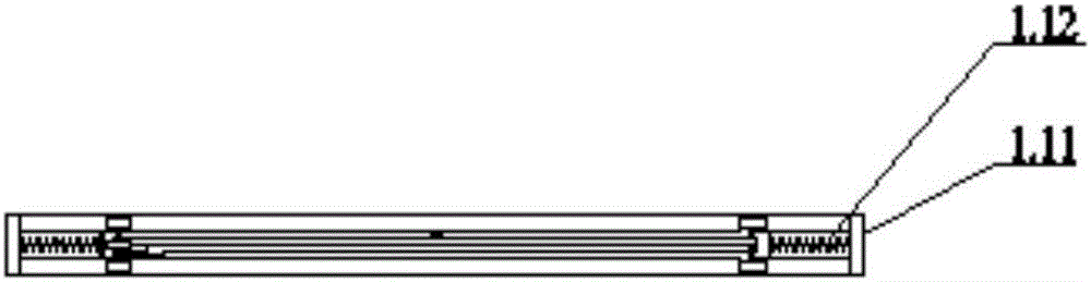
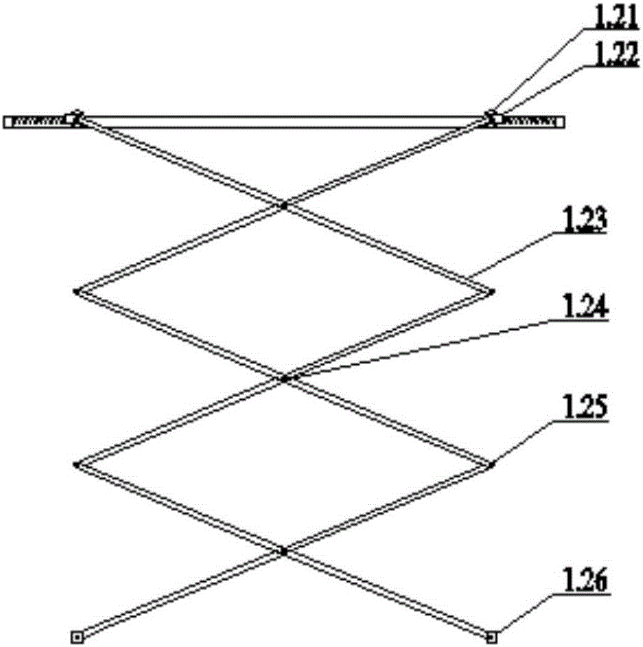
[0063] When moving the aerator or the river water level drops to cause the distance between the riverbed and the liquid surface to become smaller, the fixed slide rail 1.1 on the solar aerator moves down relative to the weight 2.6, and the pulley on the mechanical arm 1.2 pulls the spring 1.12 on one side The pulling force is greater than the pulling force provided by the steel cable III, and the pulley 1.21 moves outward until the force on both sides of the pulley 1.21 reaches a balance. The arm 1.2 shrinks upwards, and the shortened distance is similar to the shortened length between the weight 2.6 and the slide rail 1.1. The mechanical arm 1.2 drives the aeration branch pipe 3.3 to move upwards, and the rotating wheel 3.1 rotates to roll up the excess air delivery hose 3.2 to complete the upward movement process of the aeration branch pipe 3.3.

[0064] W...

Embodiment 2

[0066] When the river is rising:

[0067]The fixed slide rail 1.1 on the solar aerator moves upwards relative to the weight 2.6. Since the weight 2.6 is close to being fixed on the river bed, the pulling force on one side of the pulley traction spring 1.12 on the mechanical arm 1.2 is less than the pulling force provided by the steel cable III, and the pulley 1.21 moves inward until the forces on both sides of the pulley 1.21 are balanced, and the pulley 1.21 drives the mechanical arm 1.2 to move, making the upward angle between the mechanical arms 1.2 smaller and extending the mechanical arm 1.2 downward. 2.6 is similar to the length of growth between slide rail 1.1. The mechanical arm 1.2 drives the aeration branch pipe 3.3 to move down, and the rotating wheel 3.1 rotates to release the rolled up air delivery hose 3.2 to complete the downward movement process of the aeration branch pipe 3.3.

Embodiment 3

[0069] Move the aerator to a shallower area:

[0070] The fixed slide rail 1.1 on the solar aerator moves downward relative to the weight 2.6, the pulling force on one side of the pulley traction spring 1.12 on the mechanical arm 1.2 is greater than the pulling force provided by the steel cable III 2.43, and the pulley 1.21 moves outward until the pulley 1.21 When the force on both sides is balanced, the pulley 1.21 on the mechanical arm 1.2 drives the mechanical arm 1.2 to move, so that the upward angle between the mechanical arms 1.2 becomes larger, and the mechanical arm 1.2 shrinks upwards, shrinking the distance, and the weight 2.6 and sliding The shortened lengths between rails 1.1 are similar. The mechanical arm 1.2 drives the aeration branch pipe 3.3 to move upwards, and the rotating wheel 3.1 rotates to roll up the excess air delivery hose 3.2 to complete the upward movement process of the aeration branch pipe 3.3.


PUM


Abstract

The invention discloses an automatic elevating apparatus and method of an aeration tube of a floating aerator, and belongs to the technical fields of water restoration and water treatment. The apparatus comprises a slide rail fixed on a floating aerator floating body, slidable mechanical arms are arranged at the top feet of the slide rail, the bottom foot of every mechanical arm is provided with a slidable aeration branch tube, a rope of a pulley group mechanism pulls a large fixed pulley fixed above the mechanical arm slide rail, the large fixed pulley coaxially drives a small fixed pulley having a certain ratio relative to the large fixed pulley to rotate, and the small fixed pulley controls the top feet of the X-shaped mechanical arms to move apart or close up, so a case that a rising or descending distance of the aeration branch tubes driven by the X-shaped mechanical arms is almost same to a distance of a weight moving closer to the water level is realized, and a gas conveying flexible tube is synchronously retracted or released by a gas conveying tube telescoping mechanism. The apparatus and the method allow the aeration tubes to be positioned in specific positions above the riverbed, reduce the disturbance to riverbed sediments and improve the oxygen charging efficiency.

Description

technical field [0001] The invention belongs to the technical field of water restoration and water treatment, and more specifically relates to a device and method for controlling aeration depth, improving oxygenation efficiency, and reducing sediment disturbance, especially an aeration tube for a floating aerator Automatic lifting device and method. Background technique [0002] With the rapid development of our country's economy, the increase of population, the acceleration of industrialization and urbanization, on the one hand, people's demand and dependence on water resources are increasing, on the other hand, the deterioration of water quality is becoming more and more serious, causing many The river water is hypoxic, black and smelly, and some rivers have even become sewage channels. The environmental capacity has dropped sharply. The deterioration of water quality has caused the basic extinction of fish and shrimps in the river, the structure of aquatic biological comm...

Claims


Application Information

Patent Timeline
Patent Type & Authority Applications(China)
IPC IPC(8): C02F7/00C02F3/02
CPCC02F3/02C02F7/00Y02W10/10Y02W10/37
Inventor 沈晓笑
Owner 沈晓笑
Why Eureka
Try Eureka