Foot structure of four foot walking robot with foot float support

A walking robot and floating support technology, applied in the field of robotics, can solve problems such as walking machine failure, failure to meet requirements, motor stalling, etc., and achieve the effects of reasonable design, simplified control scheme, and increased contact time

Inactive Publication Date: 2005-03-02
SHANGHAI JIAO TONG UNIV
View PDF1 Cites 26 Cited by
  • Summary
  • Abstract
  • Description
  • Claims
  • Application Information

AI Technical Summary

Problems solved by technology

[0003] After literature search, it is found that the Chinese patent publication number is: 1407922, the patent name is: legged mobile robot, method of controlling the robot, foot structure of the robot, and movable leg unit of the robot, and the application date is: November 2001 On the 16th, the foot structure described in this patent consists of three parts: a foot seat, a foot pad, and an ankle connection unit. The foot pad is composed of at least two cushioning materials arranged at predetermined positions on the bottom plate of the foot seat. different, and located on the inside and outside of the foot base plate, the characteristics of the foot and ankle connection unit are not given in this patent, but in the legged mobile robot, the feet of the quadruped walking robot and the biped walking robot are in the structural shape, The use of ankle connection units and sensors is different, so the foot structure in this patent cannot be directly applied to quadruped walking robots, and the defects of this foot structure in the actual use of quadruped walking robots are: 1. When the quadruped walking robot is walking statically, the error of the transmission chain and the driving error will cause motion interference and jamming between the supporting legs, which will cause the walking machine to fail, cause the motor to stall or burn out, and the foot structure cannot compensate for the transmission. Chain error and drive error
2. When the quadruped walking robot walks dynamically in a diagonal trot state, when the robot moves faster, the four legs are in the swing phase at the same time, and the four legs are in the air at the same time. This alternating process requires the robot mechanism to have elasticity and vibration reduction functions , the foot structure does not meet the requirements of the elastic mechanism for this movement
3. The walking robot is in constant contact with the walking surface when walking, and the reaction force from the walking surface becomes a large impulse force, which becomes a kind of interference and causes the robot to be unstable. The foot structure cannot effectively absorb this impulse force

Method used


Image

  • Foot structure of four foot walking robot with foot float support
  • Foot structure of four foot walking robot with foot float support
  • Foot structure of four foot walking robot with foot float support

Examples


Embodiment Construction

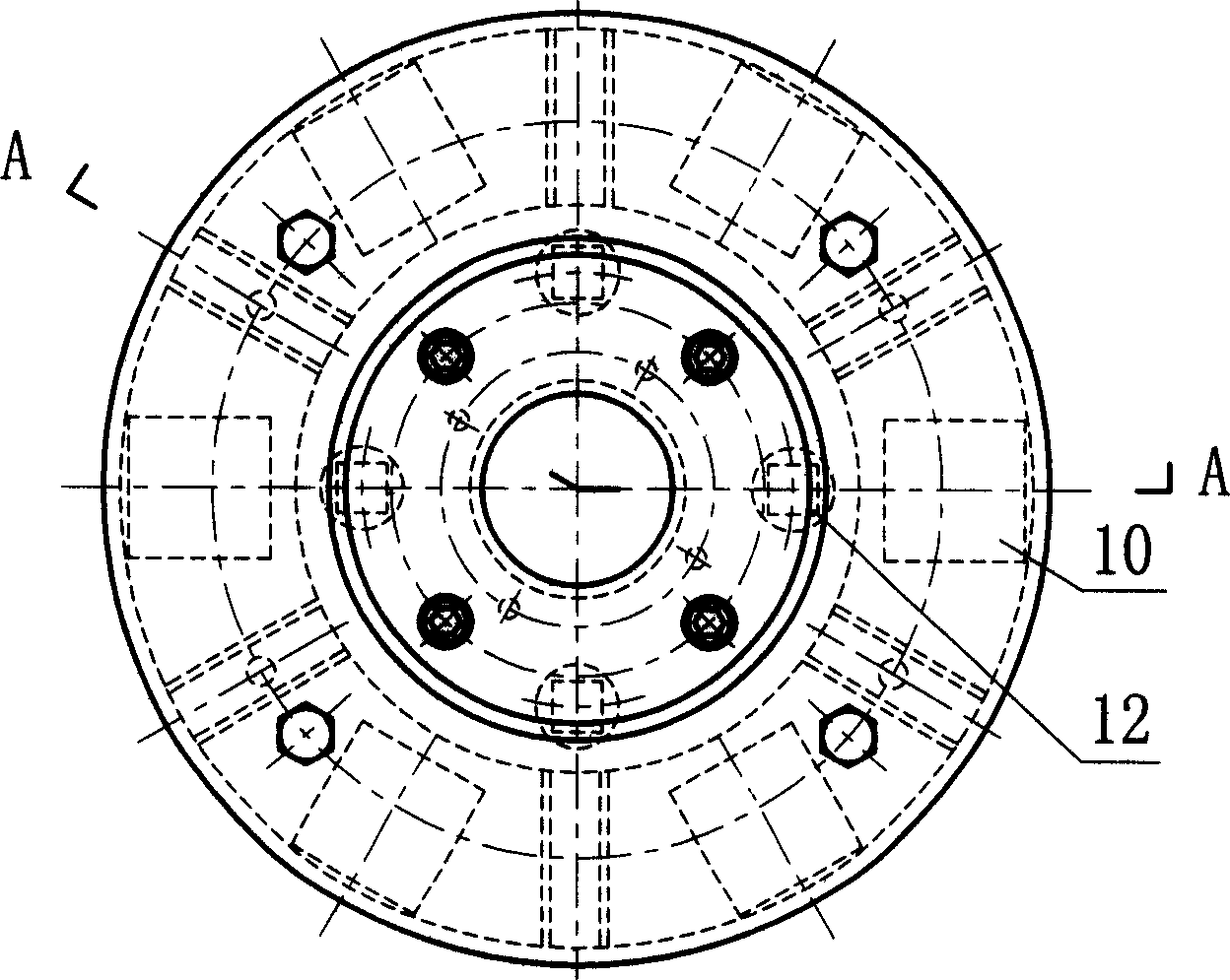
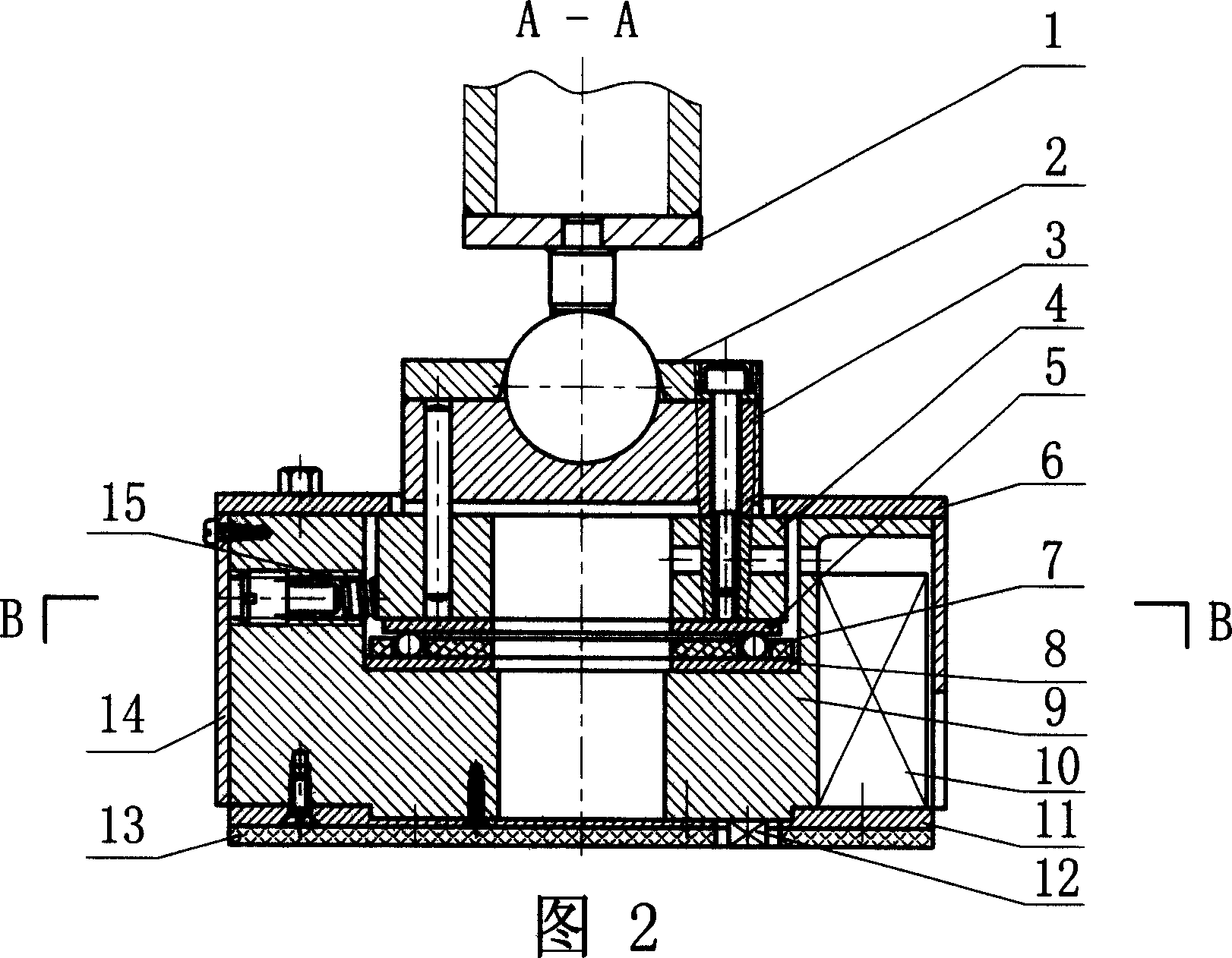
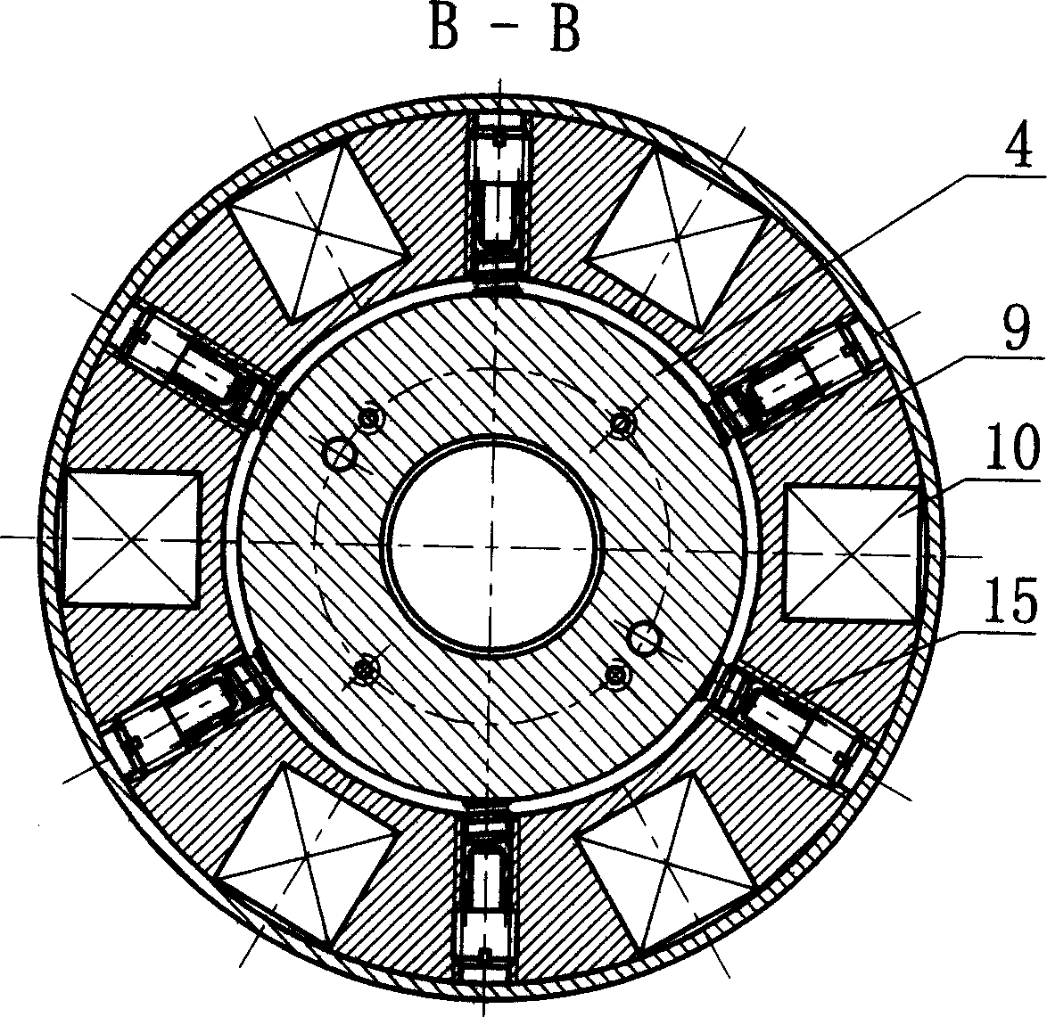
[0017] like Figure 1-4 As shown, the present invention includes: shank 1, spherical secondary cover plate 2, joint 3, instep seat 4, upper gasket 5, pressure plate 6, ball 7 with cage, lower gasket 8, sole seat 9, proximity sensor 10 , Foot pad 11, tactile sensor 12, buffer pad 13, jacket 14, stage clip 15.

[0018] The joint 3, the instep seat 4 and the upper gasket 5 are fixedly connected by pins and threads to form the instep of the member, the lower gasket 8 and the sole seat 9 are fixedly connected by the thread to form the sole of the member, and the instep is connected to the calf 1 through a spherical pair, and the spherical auxiliary cover The plate 2 is connected on the instep to form a part of the spherical pair. The sole of the foot is connected on the instep through a radial moving pair. The ball 7 with a cage is connected between the two contact surfaces of the moving pair. The two ends of the compression spring 15 respectively press On the outer cylindrical su...


PUM


Abstract

The foot structure of four foot waling robot with floated foot support includes calf, subsidiary ball cover plate, knuckle, instep seat, upper washer, clamp plate, balls in holder, lower washer, sole seat, approach sensor, foot pad, feeling sensor, buffering pad, outer casing and pressing spring connected together. The present invention is light, firm and floatable, and has elastic compensation capacity and environment feeling capacity.

Description

technical field [0001] The invention relates to a foot structure of a robot, in particular to a foot structure of a quadruped walking robot supported by floating feet, which is used in the field of robots. Background technique [0002] Walking robots have obvious advantages in crossing obstacles, passing through rough terrain, soft ground and mobility flexibility, and quadruped walking robots are an important branch of robots. The quadruped walking robot has stronger carrying capacity and better stability than the biped walking robot, and is simpler in structure than the hexapod and eight-leg walking robots. [0003] After literature search, it is found that the Chinese patent publication number is: 1407922, the patent name is: legged mobile robot, method of controlling the robot, foot structure of the robot, and movable leg unit of the robot, and the application date is: November 2001 On the 16th, the foot structure described in this patent consists of three parts: a foot ...

Claims


Application Information

Patent Timeline
Patent Type & Authority Applications(China)
IPC IPC(8): B62D57/032
Inventor 胡贯朋马培荪高雪官
Owner SHANGHAI JIAO TONG UNIV
Why Eureka
Try Eureka