Sublimation bed employing carrier gas guidance structures

a guidance structure and sublimation bed technology, applied in the direction of coatings, metallic material coating processes, chemical vapor deposition coatings, etc., can solve the problems of poor vapor/solid contact time, insufficient ratio of solid source surface area to vapor volume, and progressively more difficult to saturate the carrier gas. , to achieve the effect of increasing the ratio of exposed solid source surface area and increasing the vapor/solid contact tim

Inactive Publication Date: 2006-09-28
SHERO ERIC J +2
View PDF17 Cites 24 Cited by
  • Summary
  • Abstract
  • Description
  • Claims
  • Application Information

AI Technical Summary

Benefits of technology

[0012] A feature of preferred embodiments of the present invention is that a precise and consistent quantity of reactant vapor can be delivered to a deposition chamber at high frequency. An additional feature of the preferred embodiments is an increased ratio of exposed solid source surface area to sublimation vessel volume as a result of, among other factors, the avoidance of problematic “tunneling.” Another feature of preferred embodiments is increased vapor / solid contact time. Yet another feature of preferred embodiments is the allowance of relatively even gas flow resistance over the life of a sublimation bed. Another feature of certain preferred embodiments is the production of a substantially plug flow residence time distribution of the carrier gas substantially saturated with precursor vapor.

Problems solved by technology

Unfortunately, existing semiconductor processing systems, of which a sublimation apparatus is a component, have a number of shortcomings including offering both an inadequate ratio of solid source surface area to vapor volume, and poor vapor / solid contact time.
In addition, a conventional sublimation bed, which seeks to increase vapor / solid contact time, is often prone to “tunneling.” Tunneling results from the tendency of gas to flow preferentially along low resistance paths, rather than through the bulk of the powder, such that progressively smaller solid precursor surface area is exposed to the gas flow as the tunnel through the powder widens.
It is thus progressively more difficult to saturate the carrier gas, even though the sublimation bed contains plenty of unvaporized solid source powder.

Method used


Image

  • Sublimation bed employing carrier gas guidance structures
  • Sublimation bed employing carrier gas guidance structures
  • Sublimation bed employing carrier gas guidance structures

Examples


example 1

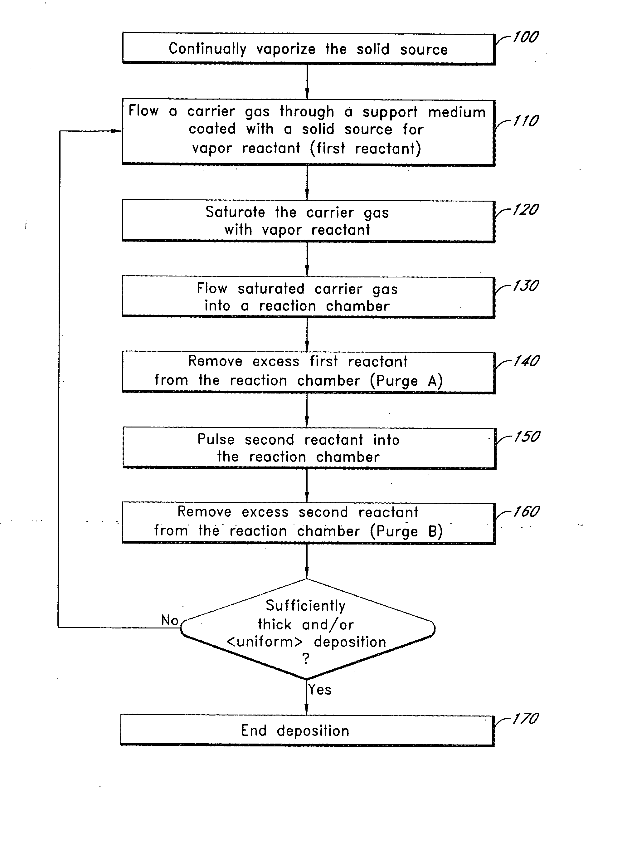
[0140] In preferred embodiments of the present invention, the effective bed length is increased greatly without necessitating a proportionate increase in the length of the sublimation vessel. This increase in effective length is facilitated by guidance structures, including support elements coated with solid source material and flow guides, each of the guidance structures being configured to channel the carrier gas through contact pathways designed to saturate the carrier gas over a relatively short distance (as measured by the direct distance between the carrier gas inlet and the outlet) and to expose the carrier gas to a large surface area of subliming solid source material.

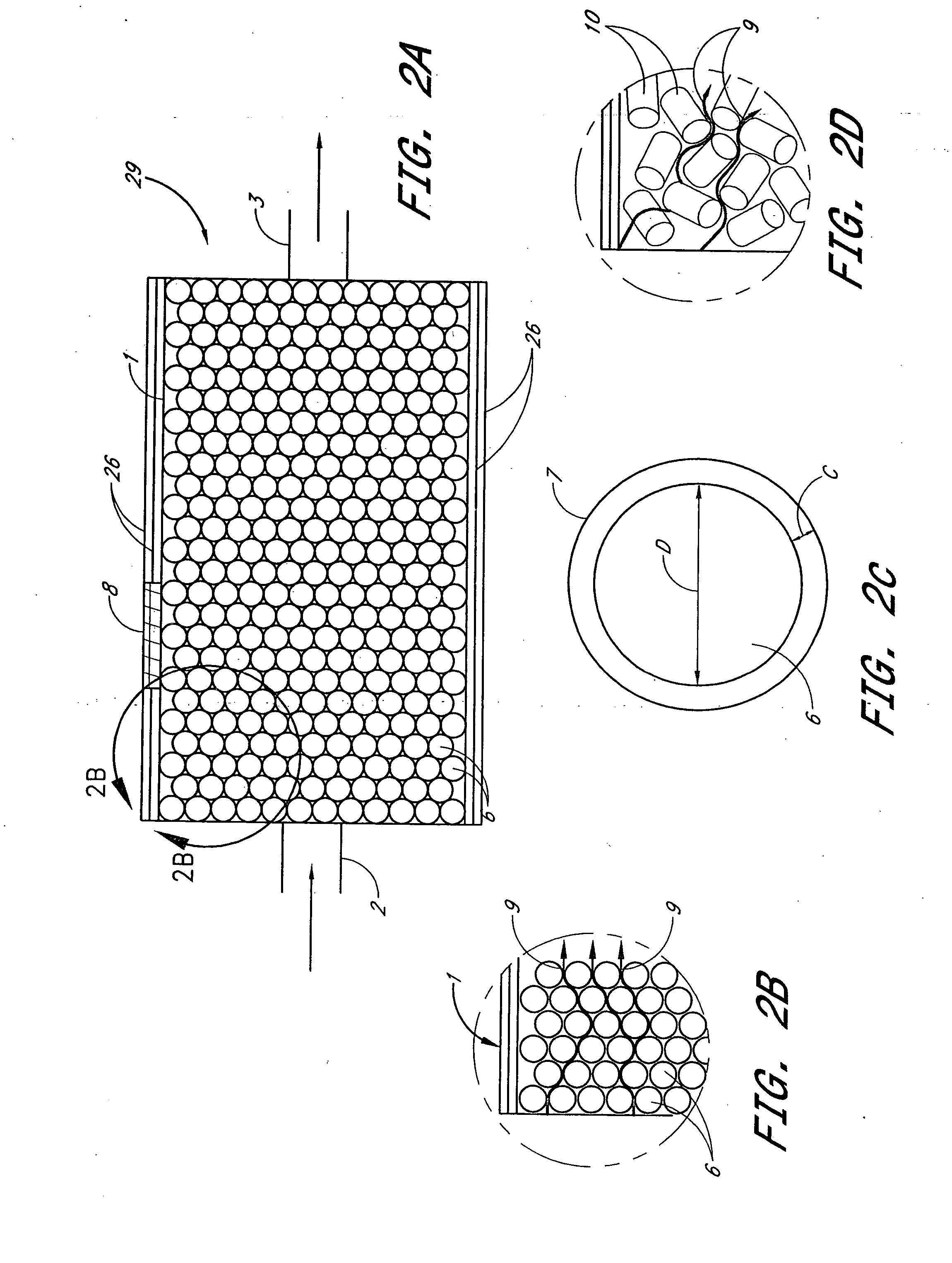
[0141] A non-limiting example of potential sublimation bed parameters made possible by solid source coated beads, or spheres, as determined by the Alcoa CSS computer program, follows in Table 1:

TABLE 1Potential Sublimation Bed Parameters Using Non-Porous Spheresand an HfCl4 CoatingSphere Diameter (mm)4Bed Di...

example 2

[0143] In certain preferred embodiments, the sublimation bed is capable of producing a substantially plug flow, i.e. approaches an ideal plug flow. One advantage of configuring preferred embodiments to flow a substantial plug flow is that ideal plugged flow residence time distribution (or plug flow mixing behavior) effectuates a concentration at the vessel outlet which stays constant with time up to the vessel residence time (V / Q, where V=−vessel volume and Q is the volumetric flow rate). If you make the residence time of the reactor much longer than the pulse time, the entire pulse length will remain at Csat. Therefore, if reactor or vessel (holding the powder or precursor coated support medium) is long and / or convoluted (e.g., coiled path, helically guided path, tortuous path through coated beads, etc), then the residence time is high. Advantageously, in preferred embodiments employing ALD, each pulse of flow into the vessel will preferably push a “slice” of carrier gas saturated ...

example 3

[0146] The preferred embodiments shown in FIGS. 15-20B were modeled and the results are represented by the plot shown in FIG. 24, showing the residence time distribution (RTD) curve for the vessel with shelves. The plot shown in FIG. 24 is the result of a fluid mechanical modeling of packed vessel embodiments and it shows that the RTD is very close to that of an ideal PFR. The individual data points are shown in Table 4 below. The plotted results substantially equates to a dispersion model with a very low DL / uL. In other words, the resulting curve is similarly shaped to the plug flow curve in FIG. 23. This plotted curve shows the response of the vessel to a step function change in concentration at the inlet. This is the J(theta), or Residence Time Distribution (RTD) function. Its conventional definition is the fraction of the effluent stream having a residence time less than theta.

[0147] Co is the concentration of the tracer fluid step at the inlet and C is its concentration at the...


PUM

PropertyMeasurementUnit
timeaaaaaaaaaa
vapor pressureaaaaaaaaaa

Abstract

Preferred embodiments of the present invention provides a sublimation system employing guidance structures including certain preferred embodiments having a high surface area support medium onto which a solid source material for vapor reactant is coated. Preferably, a guidance structure is configured to facilitate the repeated saturation of the carrier gas with the solid source for a vapor reactant. Methods of saturating a carrier gas using guidance structures are also provided.

Description

REFERENCE TO RELATED APPLICATION [0001] The present application is a divisional of U.S. patent application Ser. No. 10 / 629,029, filed Jul. 29, 2003, which claims the priority benefit under 35 U.S.C. § 119(e) of Provisional Application No. 60 / 400,210, filed on Jul. 30, 2002, both of which are incorporated herein by reference in their entireties. The present application is related to U.S. patent application Ser. No. 10 / 463,309, filed on Jun. 16, 2003, which is incorporated herein by reference in its entirety.FIELD OF THE INVENTION [0002] The present invention relates generally to the field of substrate fabrication and, more specifically, to semiconductor processing apparatuses designed to effectively vaporize a solid source material. BACKGROUND AND SUMMARY OF THE INVENTION [0003] In the fabrication of integrated circuits on substrates, such as semiconductor wafers, the vapor deposition of chemicals, such as chemical vapor deposition (“CVD”) and more recently atomic layer deposition (A...

Claims


Application Information

Patent Timeline
Patent Type & Authority Applications(United States)
IPC IPC(8): C23C16/00C23C16/44C23C16/448C23C16/455H01L21/31
CPCC23C16/4481C23C16/45544C23C16/4483C23C16/448
Inventor SHERO, ERIC J.GIVENS, MICHAEL E.SCHMIDT, RYAN
Owner SHERO ERIC J
Why Eureka
Try Eureka