Lamp

a technology for lamps and adjusting members, applied in the field of lamps, can solve the problems of disordered visual effect in space, damage to externally exposed adjusting members, etc., and achieve the effect of keeping the appearance of the exterior of the lamp unchanged

Active Publication Date: 2018-03-27
RADIANT OPTO ELECTRONICS
View PDF16 Cites 4 Cited by
  • Summary
  • Abstract
  • Description
  • Claims
  • Application Information

AI Technical Summary

Benefits of technology

[0007]One object of the present invention is to provide a lamp having built-in adjusting members. Therefore, when the light emitting direction of the lamp is changed, the exterior appearance of the lamp can be kept unchanged.
[0009]According to an embodiment of the present invention, the lamp further comprises a lamp base, a case body and a spherical shell. The light source is disposed on the spherical shell. The rotary adjustment mechanism connects the lamp base and the case body, thereby enabling the case body to rotate relative to the lamp base along the first direction in the first plane. The inclination adjustment mechanism connects the case body to the spherical shell, thereby enabling the spherical shell to rotate relative to the case body along the second direction in the second plane.
[0010]According to the aforementioned object, another lamp is provided. The lamp includes a lamp base, a case body, a rotary adjustment mechanism, a spherical shell, an inclination adjustment mechanism and a light source. The case body has a first inner space and an opening. The rotary adjustment mechanism connects the lamp base and the case body, thereby enabling the case body to rotate relative to the lamp base along a first direction in a first plane. The spherical shell is partially disposed in the first inner space and partially extends out of the opening. The inclination adjustment mechanism connects the case body to the spherical shell, thereby enabling the spherical shell to rotate relative to the case body along a second direction in a second plane, wherein the second plane is different from the first plane. The light source is disposed on the spherical shell.
[0029]According to the above embodiments, the lamp of the present invention includes the rotary adjustment mechanism and the inclination adjustment mechanism, thereby enabling a user to rotate the case body relative to the lamp base or to rotate the spherical shell relative to the case body, thus changing a light emitting direction of the lamp to meet different illumination requirements. In addition, the rotary adjustment mechanism and the inclination adjustment mechanism are hidden internally, so that the exterior appearance of the lamp can be kept unchanged when the light emitting direction of the lamp is changed. Therefore, when multiple lamps with different light emitting directions are applied in the same space, each lamp has the same exterior appearance to make the visual effect in the space look more simple and organized.

Problems solved by technology

The externally-exposed adjusting members are likely to be damaged due to long term exposure to the moisture or dust in the ambience.
Furthermore, when multiple projecting lamps are used in the same space, if the rotation and light emitting direction of multiple projecting lamps are different from each other, a disordered visual effect in the space will be resulted in.

Method used


Image

  • Lamp
  • Lamp
  • Lamp

Examples


first embodiment

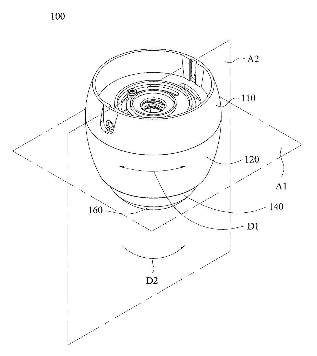
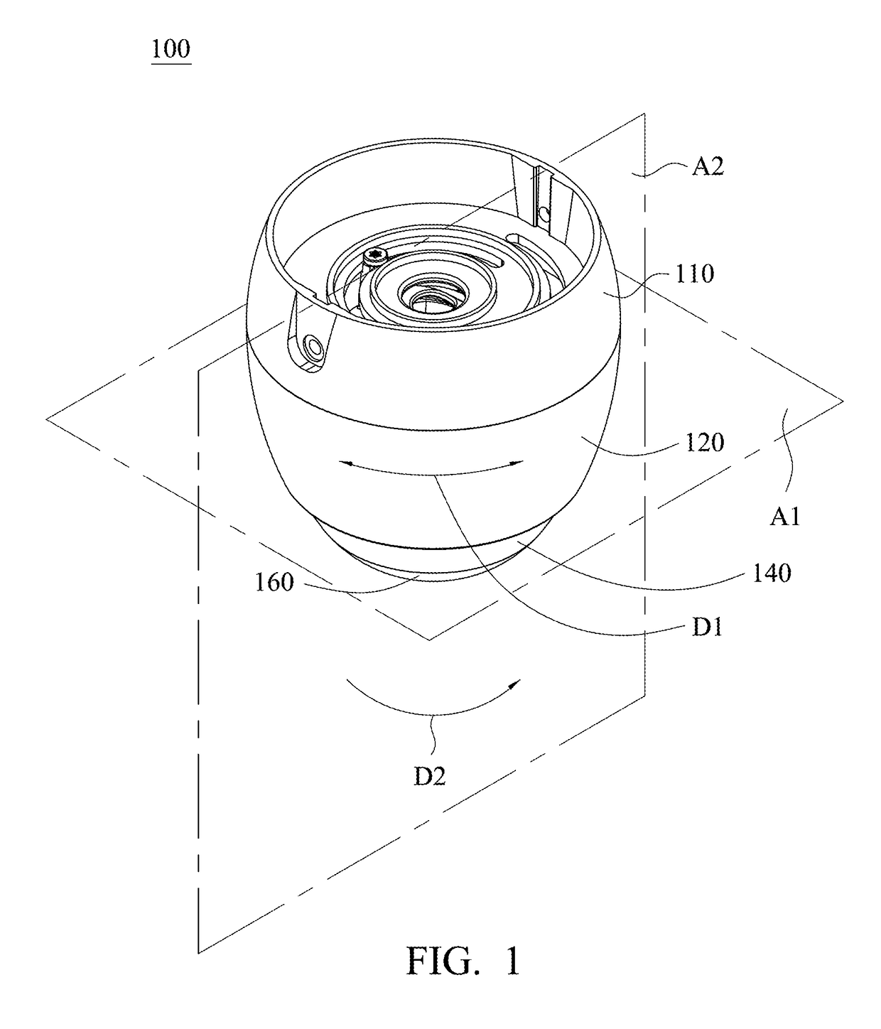
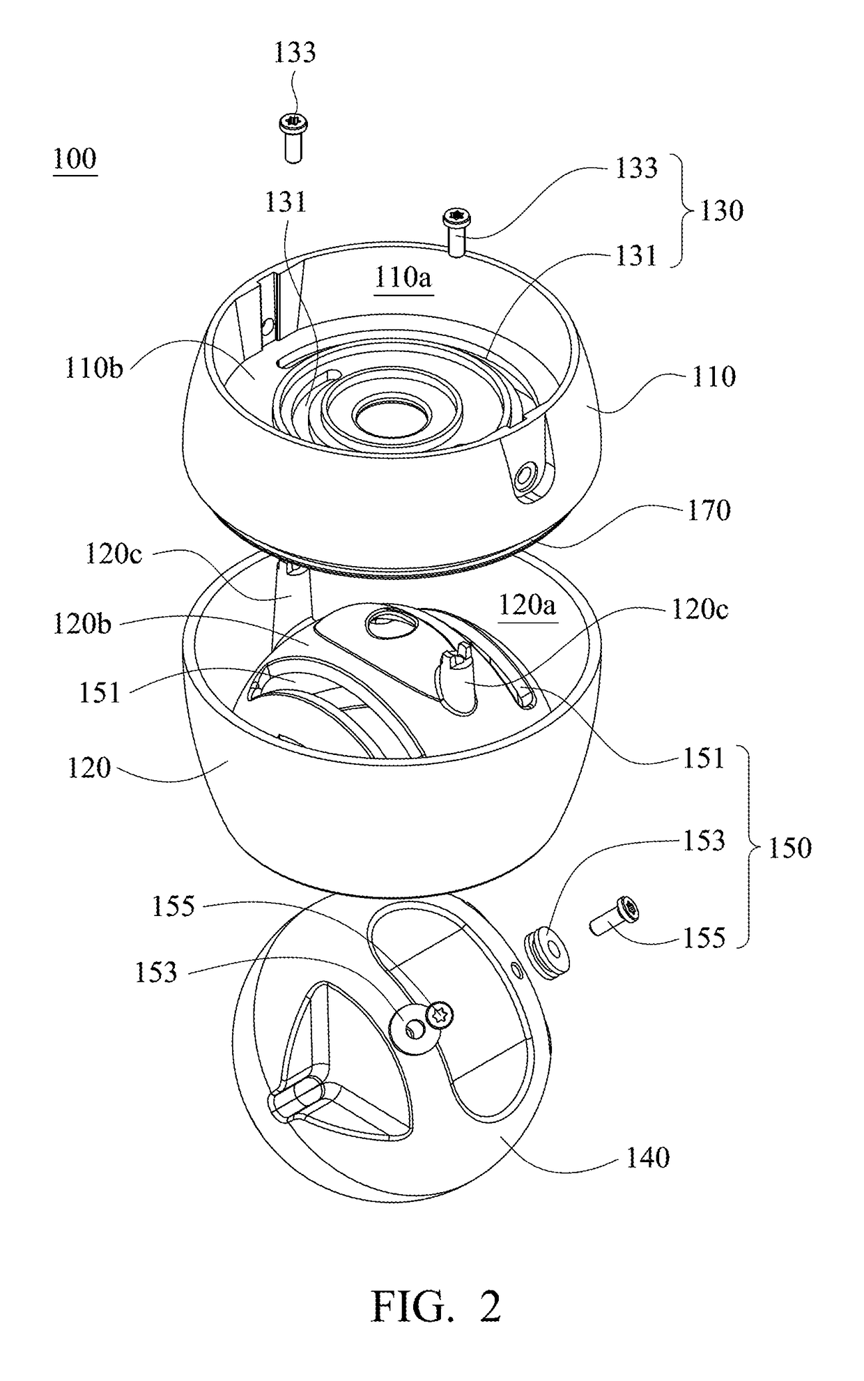
[0060]Simultaneously referring to FIG. 1 and FIG. 2, FIG. 1 and FIG. 2 are a schematic diagram and a schematic exploded view showing a lamp 100 in accordance with the present invention. The lamp 100 mainly includes a rotary adjustment mechanism 130, an inclination adjustment mechanism 150 and a light source 160. As shown in FIG. 1, the light source 160 is rotatable along a first direction D1 in a first plane A1 by the rotary adjustment mechanism 130 and / or rotatable relative along a second direction D2 in a second plane A2 by the inclination adjustment mechanism 150. In the present embodiment, the second plane A2 is different from the first plane A1. As shown in FIG. 1 and FIG. 2, the lamp 100 further includes a lamp base 110, a case body 120 and a spherical shell 140. The rotary adjustment mechanism 130 is disposed in an inner space 110a of the lamp base 110 and / or an inner space 120a of the case body 120, and the rotary adjustment mechanism 130 can be used to connect the lamp base...

second embodiment

[0070]In the present invention, the lamp 100 may have different designs. Referring to FIG. 10 to FIG. 12, FIG. 10 to FIG. 12 are a schematic diagram, a schematic exploded view showing and a partial cross-sectional view showing a lamp 300 in accordance with the present invention. The lamp 300 mainly includes a rotary adjustment mechanism 330, an inclination adjustment mechanism 350 and a light source 360. As shown in FIG. 10, the light source 360 is rotatable along a first direction D3 in a first plane A3 by the rotary adjustment mechanism 330 and / or rotatable relative along a second direction D4 in a second plane A4 by the inclination adjustment mechanism 350. In the present embodiment, the second plane A4 is different from the first plane A3. As shown in FIG. 10 to FIG. 12, the lamp 300 further includes a lamp base 310, a case body 320 and a spherical shell 340. The rotary adjustment mechanism 330 is mainly disposed in an inner space 310a of the lamp base 310 and / or an inner space ...

third embodiment

[0078]In the present invention, the lamp 300 may have different designs. Referring to FIG. 16 to FIG. 18, FIG. 16 to FIG. 18 are a schematic diagram, a schematic exploded view and a partial cross-sectional view showing a lamp 500 in accordance with the present invention. The lamp 500 mainly includes a rotary adjustment mechanism 530, an inclination adjustment mechanism 550 and a light source 560. As shown in FIG. 1, the light source 560 is rotatable along a first direction D5 in a first plane A5 by the rotary adjustment mechanism 530 and / or rotatable relative along a second direction D6 in a second plane A6 by the inclination adjustment mechanism 550. In the present embodiment, the second plane A6 is different from the first plane A5. As shown in FIG. 16 to FIG. 18, the lamp 500 further includes a lamp base 510, a case body 520 and a spherical shell 540. The rotary adjustment mechanism 530 is disposed in an inner space 510a of the lamp base 510 and / or an inner space 520a of the case...


PUM


Abstract

A lamp includes a rotary adjustment mechanism, an inclination adjustment mechanism and a light source. The light source is rotatable along a first direction in a first plane by the rotary adjustment mechanism and / or rotatable relative along a second direction in a second plane by the inclination adjustment mechanism, wherein the second plane is different from the first plane.

Description

RELATED APPLICATIONS[0001]This application claims priority to Taiwan Application Serial Number 104107956, filed Mar. 12, 2015, which is herein incorporated by reference.BACKGROUND[0002]Field of Invention[0003]The present invention relates to an illuminating device. More particularly, the present invention relates to a lamp.[0004]Description of Related Art[0005]Besides for illumination, a lamp also can be used for creating atmosphere of an interior space. Projecting lamp has a function of adjusting different light emitting directions, and thus many people like to use the projecting lamp to build atmosphere of home or public.[0006]However, adjusting members of the projecting lamps mostly are externally exposed, thereby allowing users to change light emitting directions of the projecting lamps. The externally-exposed adjusting members are likely to be damaged due to long term exposure to the moisture or dust in the ambience. Furthermore, when multiple projecting lamps are used in the s...

Claims


Application Information

Patent Timeline
Patent Type & Authority Patents(United States)
IPC IPC(8): F21V21/30F21V14/02
CPCF21V14/02F21V21/30
Inventor HSIEH, CHIEN-MINJU, CHIH-HUNGHUANG, GUO-HAO
Owner RADIANT OPTO ELECTRONICS
Why Eureka
Try Eureka