Bracket for external fixation of bones

a bracket and bone technology, applied in the field of brackets for external fixation of broken bones, can solve the problems of small bone fracture, finger fracture, and insufficient room to use these still too bulky fixations, and achieve the effect of easy visualization of fractures

Active Publication Date: 2018-04-10
HIRSCH DYNAMICS HLDG AG
View PDF73 Cites 2 Cited by
  • Summary
  • Abstract
  • Description
  • Claims
  • Application Information

AI Technical Summary

Benefits of technology

[0006]It is therefore an object of the invention to provide a bracket for attaching the pins or screws extending from the bone fragments to an external rod. It is another object of the invention to provide a fixation system that is simple and inexpensive to use, and is effective for fixing fractures in small bones.
[0011]Generally, the needles are manufactured from surgical steel, titanium or other suitable metal, and the rods can be made of reinforced carbon fiber, which is invisible to X-rays, so that visualization of the fracture is easier.

Problems solved by technology

But there is a problem with fractures of small bones, especially fractured fingers.
However, there is in most cases not enough room to use these still too bulky fixations.
But the glues are difficult to handle and require a lot of preparation time as they are usually 2-component systems.
And after the glue has been applied, it takes a few minutes to harden.
During this time, the surgeon needs to assure that everything stays in the correct position, which is difficult and time-consuming.

Method used


Image

  • Bracket for external fixation of bones
  • Bracket for external fixation of bones
  • Bracket for external fixation of bones

Examples


Embodiment Construction

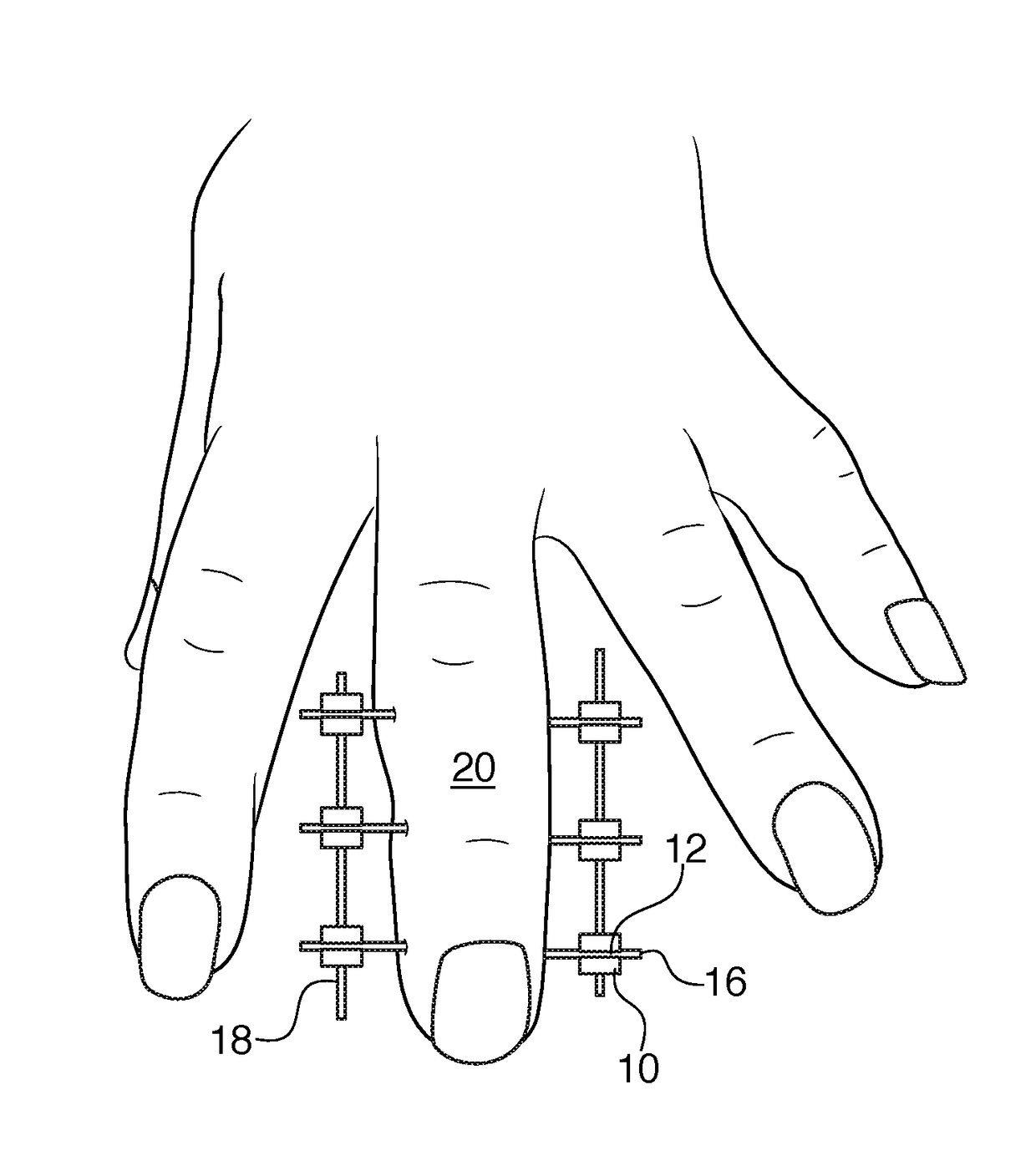
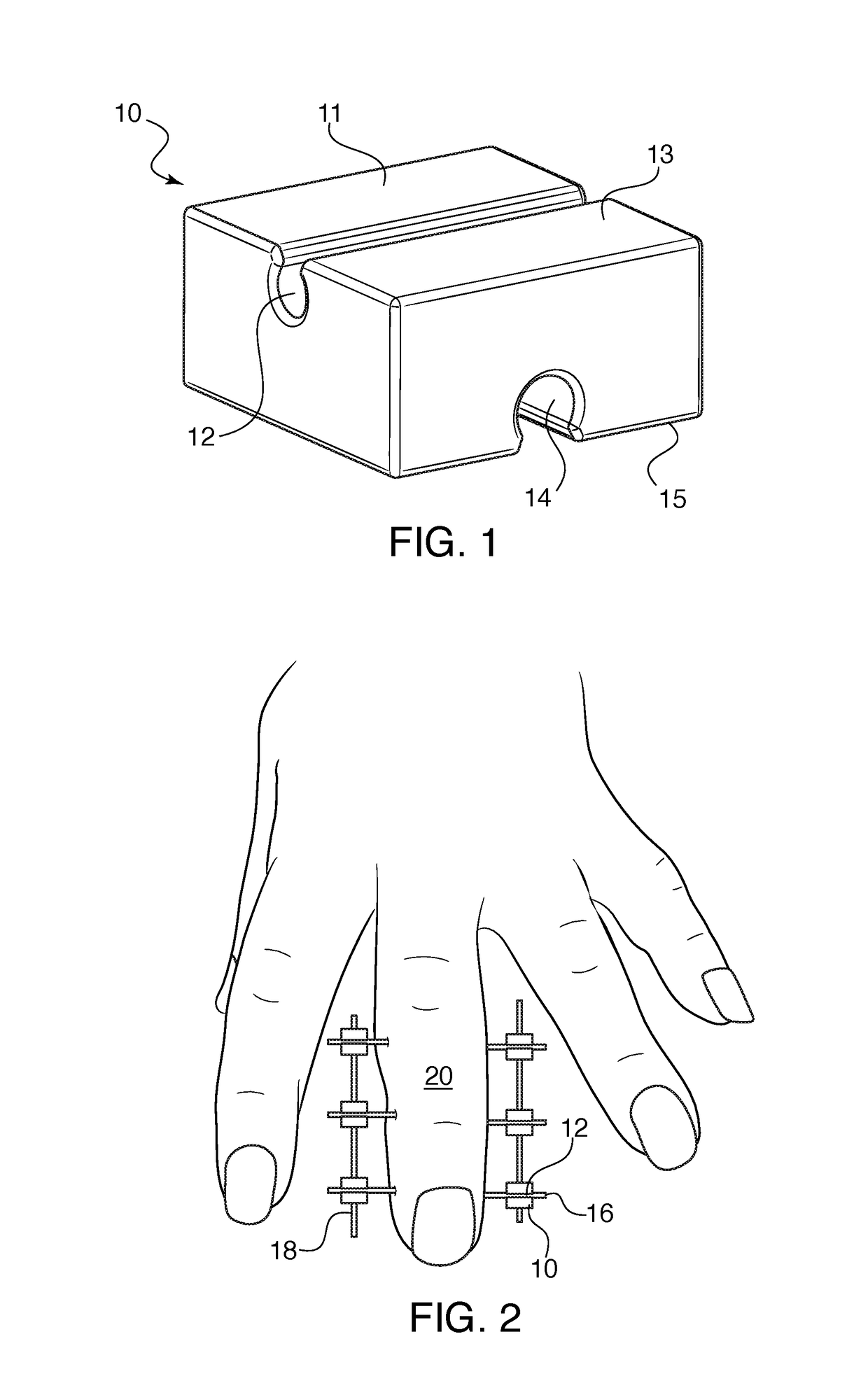
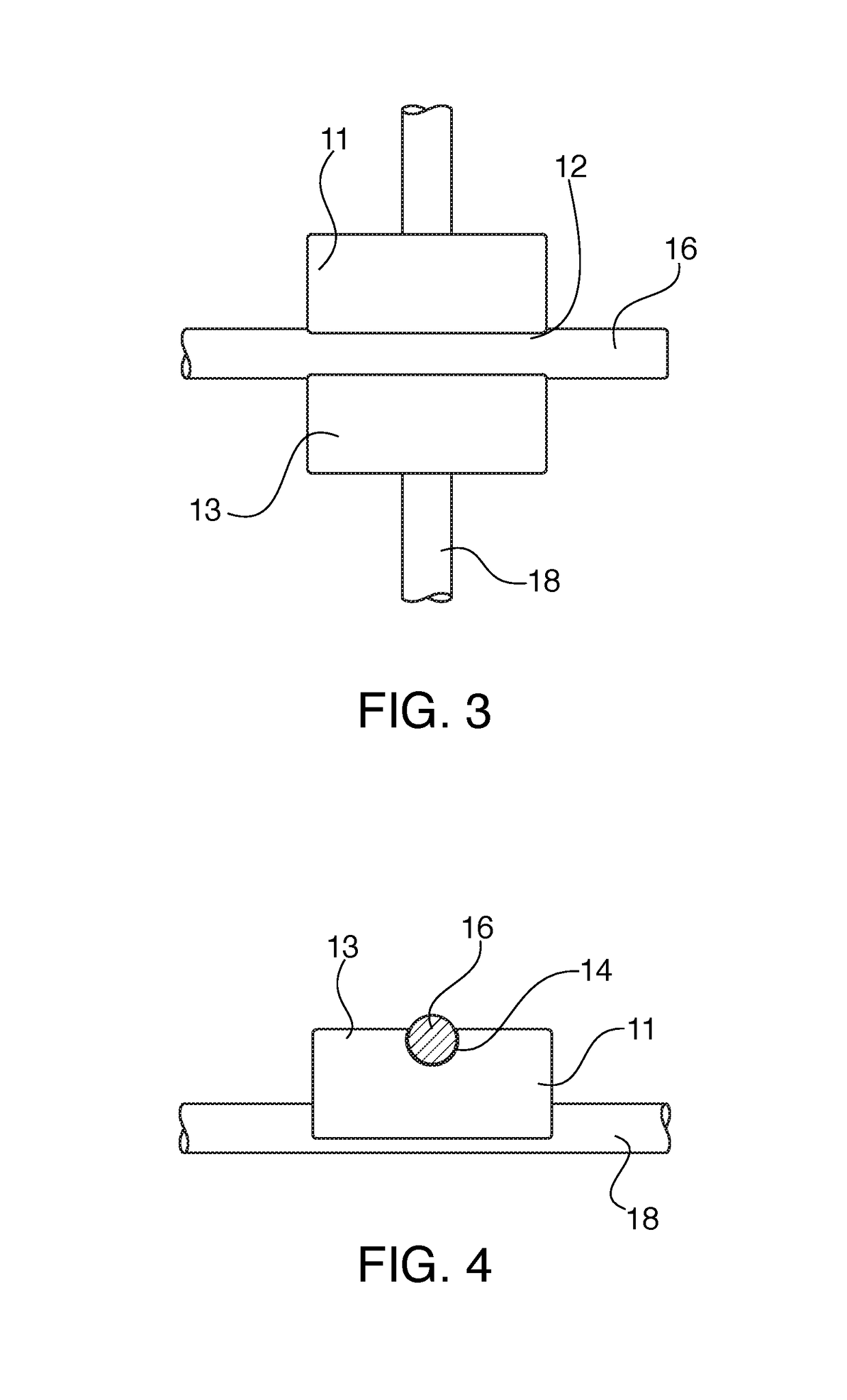
[0018]Referring now in detail to the drawings, FIG. 1 shows the bracket 10 for use in the system according to the invention. Bracket 10 consists of a block 11 having a first channel 12 located on a first surface 13, and a second channel 14 located on a second surface 15. Surface 13 and surface 15 are located on opposite sides of block 11. Channel 12 and channel 14 extend perpendicular to each other. The shape of channels 12 and 13 is roughly circular, with the opening onto surfaces 13 and 15 being smaller than a diameter of the respective channel. This shape ensures that a needle or rod inserted into the channel is retained in the channel. Block 11 is preferably formed from polyurethane, but other materials could be used. Block 11 is preferably molded and can be manufactured by 3D printing a model, pouring silicone around the model in a mold to create the mold cavity, and then molding the block using polyurethane in the silicone mold. Any other suitable manufacturing methods could b...


PUM


Abstract

A fixation system for fixing a bone fracture has a plurality of blocks, needles and rods that snap together in a framework around the fracture. The needles are inserted through the bone on opposite sides of the fracture and the blocks are snapped onto the ends of the needles. Rods are snapped onto the blocks on both sides of the finger to keep the finger in place. Each block has two channels located on opposite sides and extending perpendicular to each other. The channels are structured so that a rod or needle having a diameter equal or slightly greater than one of the channels can be snapped into and retained by the channel.

Description

CROSS-REFERENCE TO RELATED APPLICATIONS[0001]This application claims priority under 35 USC 119(e) of U.S. Provisional Application Ser. No. 62 / 301,741, filed on Mar. 1, 2016, the disclosure of which is herein incorporated by reference.BACKGROUND OF THE INVENTION[0002]1. Field of the Invention[0003]This invention relates to a bracket for external fixation of broken bones. In particular, this invention relates to a snap-on bracket that can hold the horizontal and vertical rods of the fixation brace in place.[0004]2. The Prior Art[0005]When a bone is fractured and requires fixation, the fixation can take place by attaching rods to the bone fragments to put them in place for healing over time. This fixation can take place internally, such as by a rod running through the bone, or externally, via rods placed alongside the exterior of the limb or digit to be fixed. For complex bone fractures it is often necessary to fix the fractured pieces externally. There are a variety of systems availab...

Claims


Application Information

Patent Timeline
Patent Type & Authority Patents(United States)
IPC IPC(8): A61B17/00A61B17/64A61B17/56
CPCA61B17/6441A61B17/6425A61B17/6466A61B17/6433A61B2017/564A61B2017/00477
Inventor BUERGER, HEINZ
Owner HIRSCH DYNAMICS HLDG AG
Why Eureka
Try Eureka