Bracket for external fixation of bones

US20170252068A1Active Publication Date: 2017-09-07HIRSCH DYNAMICS HLDG AG
71 Cites 0 Cited by

Patent Information

Authority / Receiving Office
US · United States
Current Assignee / Owner
Publication Date
2017-09-07

Smart Images

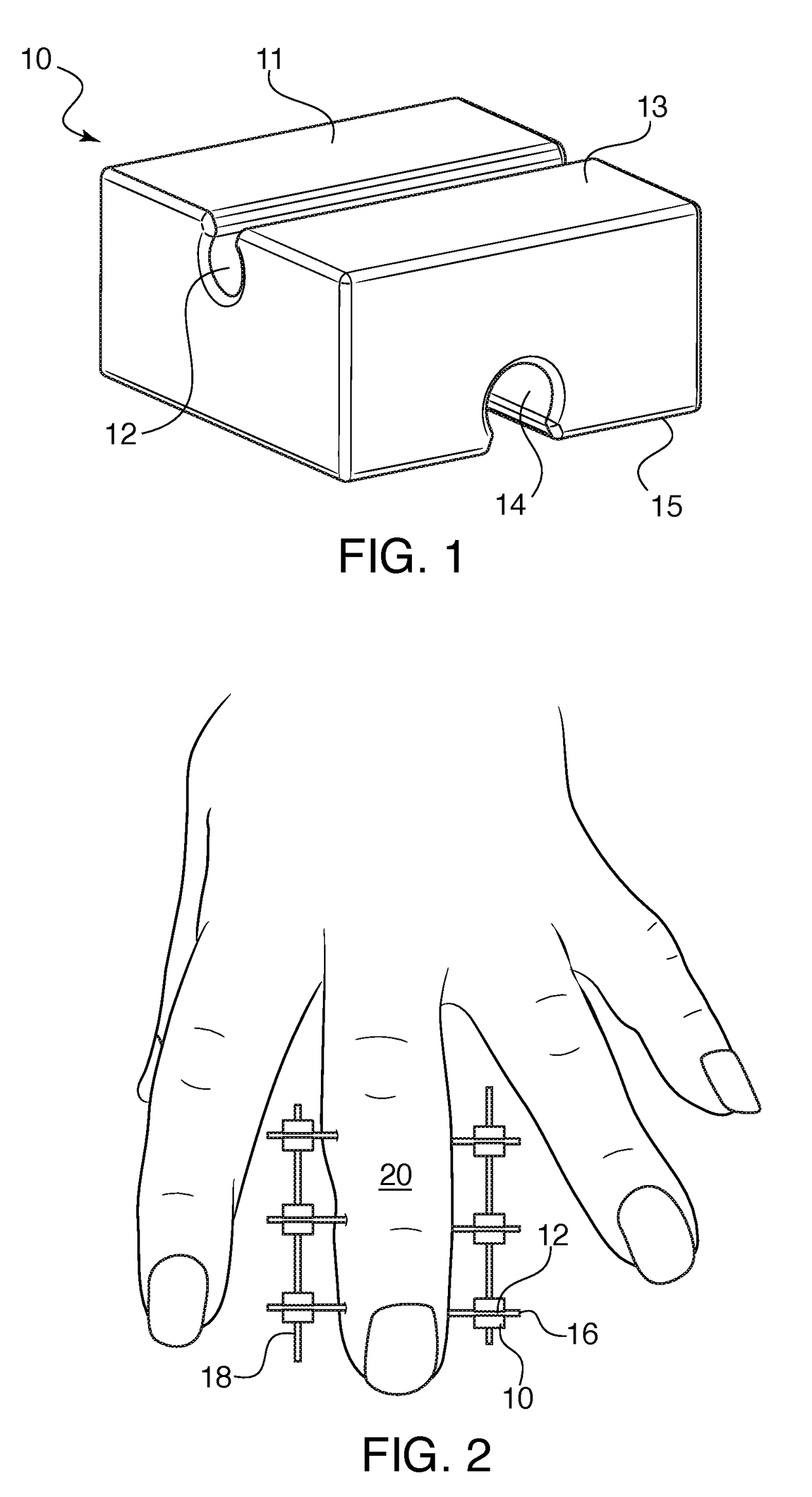
  • Figure 1
    Figure 1
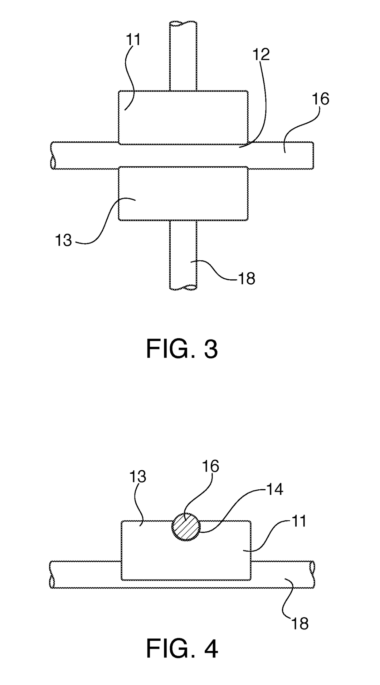
  • Figure 2
    Figure 2
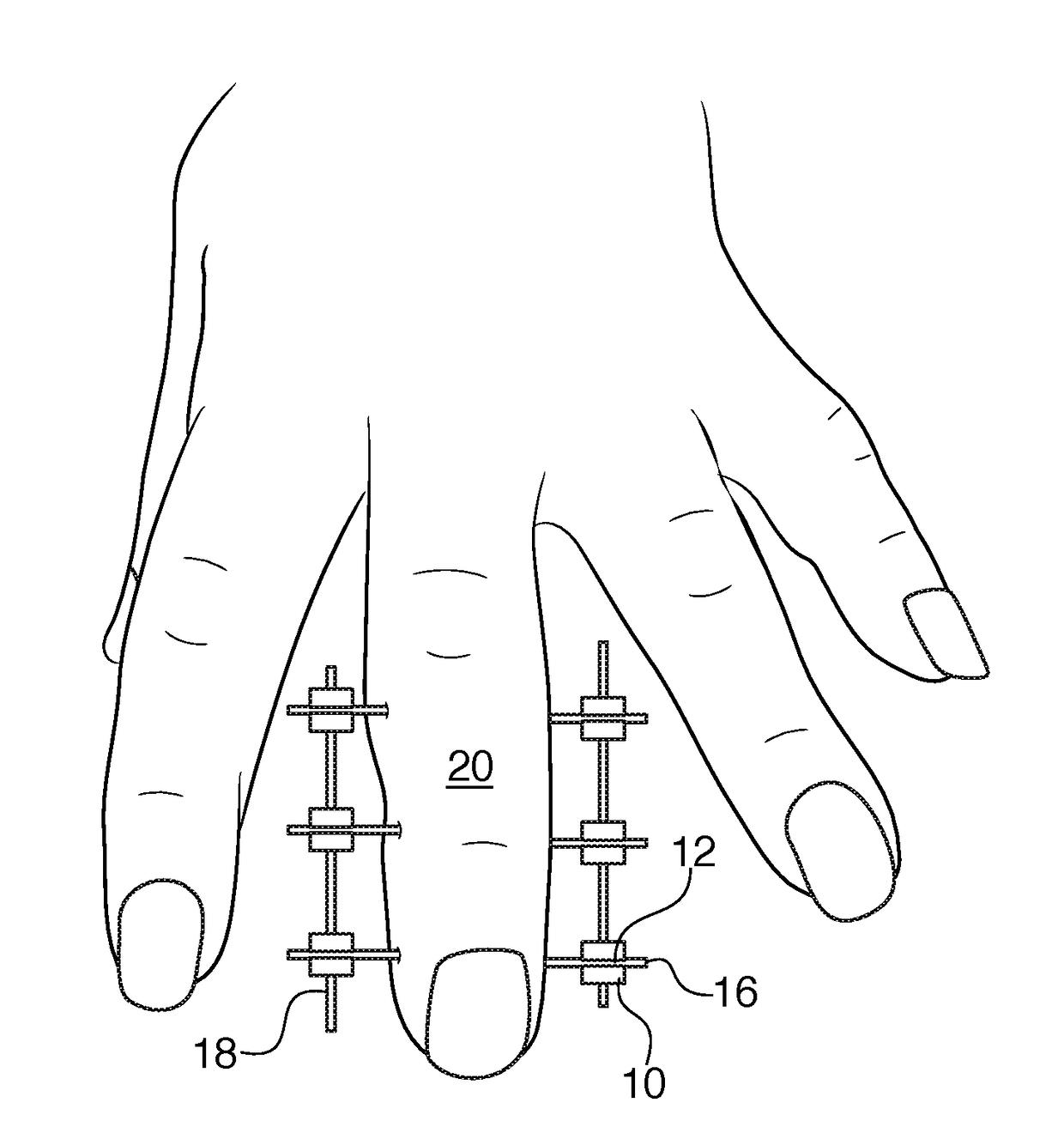
  • Figure 3
    Figure 3
Patent Text Reader

Abstract

A fixation system for fixing a bone fracture has a plurality of blocks, needles and rods that snap together in a framework around the fracture. The needles are inserted through the bone on opposite sides of the fracture and the blocks are snapped onto the ends of the needles. Rods are snapped onto the blocks on both sides of the finger to keep the finger in place. Each block has two channels located on opposite sides and extending perpendicular to each other. The channels are structured so that a rod or needle having a diameter equal or slightly greater than one of the channels can be snapped into and retained by the channel.
Need to check novelty before this filing date? Find Prior Art

Description

CROSS-REFERENCE TO RELATED APPLICATIONS

[0001] This application claims priority under 35 USC 119(e) of U.S. Provisional Application Ser. No. 62 / 301,741, filed on Mar. 1, 2016, the disclosure of which is herein incorporated by reference.BACKGROUND OF THE INVENTION

[0002] 1. Field of the Invention

[0003] This invention relates to a bracket for external fixation of broken bones. In particular, this invention relates to a snap-on bracket that can hold the horizontal and vertical rods of the fixation brace in place.

[0004] 2. The Prior Art

[0005] When a bone is fractured and requires fixation, the fixation can take place by attaching rods to the bone fragments to put them in place for healing over time. This fixation can take place internally, such as by a rod running through the bone, or externally, via rods placed alongside the exterior of the limb or digit to be fixed. For complex bone fractures it is often necessary to fix the fractured pieces externally. There are a variety of systems availab...

Examples

Embodiment Construction

[0018]Referring now in detail to the drawings, FIG. 1 shows the bracket 10 for use in the system according to the invention. Bracket 10 consists of a block 11 having a first channel 12 located on a first surface 13, and a second channel 14 located on a second surface 15. Surface 13 and surface 15 are located on opposite sides of block 11. Channel 12 and channel 14 extend perpendicular to each other. The shape of channels 12 and 13 is roughly circular, with the opening onto surfaces 13 and 15 being smaller than a diameter of the respective channel. This shape ensures that a needle or rod inserted into the channel is retained in the channel. Block 11 is preferably formed from polyurethane, but other materials could be used. Block 11 is preferably molded and can be manufactured by 3D printing a model, pouring silicone around the model in a mold to create the mold cavity, and then molding the block using polyurethane in the silicone mold. Any other suitable manufacturing methods could b...