Eureka AIR delivers breakthrough ideas for toughest innovation challenges, trusted by R&D personnel around the world.

Tubular product and manufacturing method and manufacturing device thereof

a tubular product and manufacturing method technology, applied in the field of tubular products, can solve problems such as easy fractured side sections, and achieve the effect of improving strength and rigidity of tubular products

Active Publication Date: 2011-09-20
KUNIMOTO IND CO LTD
View PDF26 Cites 2 Cited by
  • Summary
  • Abstract
  • Description
  • Claims
  • Application Information

AI Technical Summary

Benefits of technology

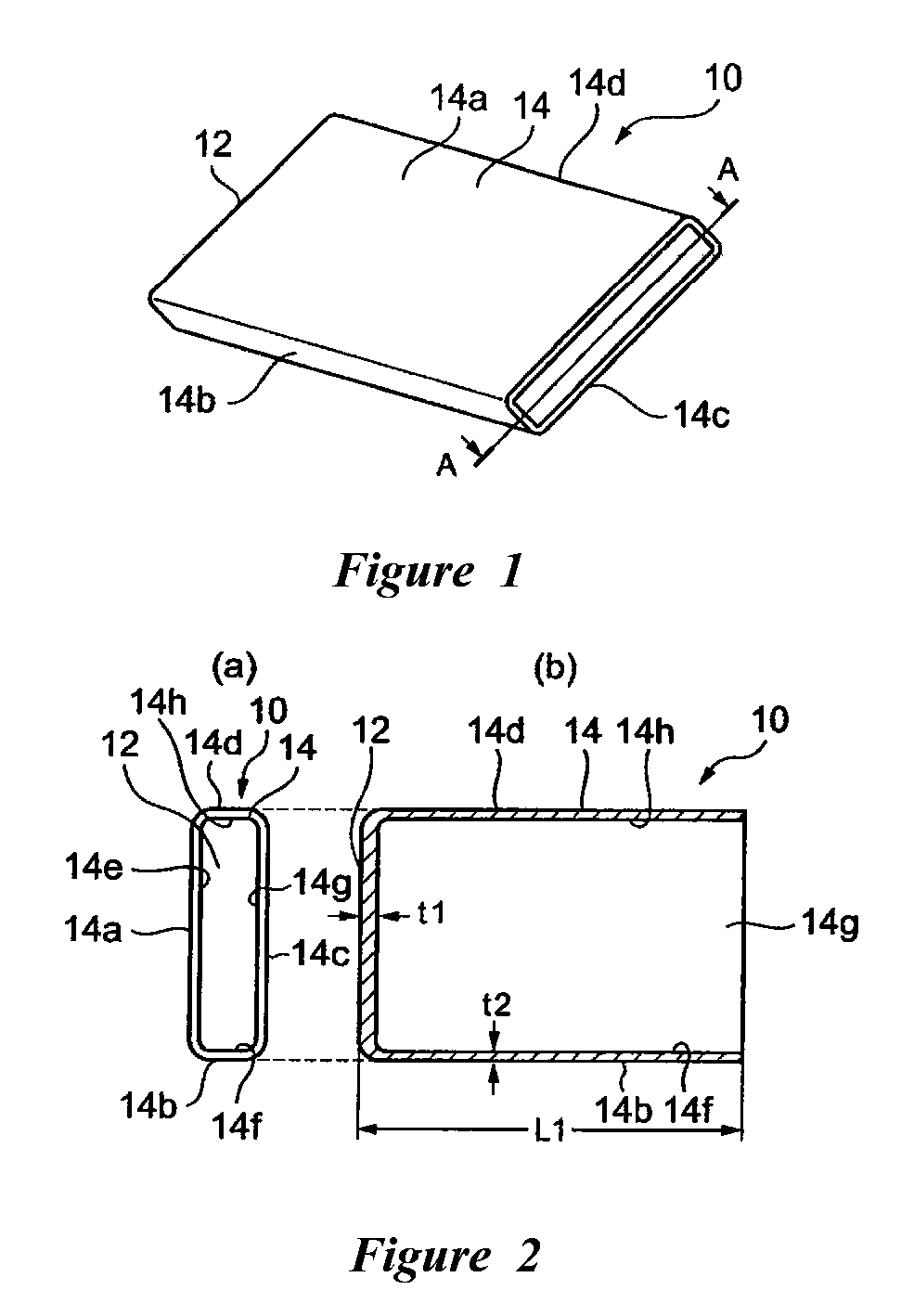
[0008]According to certain features, aspects and advantages of the present invention, a tubular product having a smooth outer surface is provided that does not easily fracture. The outer surface of the side section is not scratched by a die or any other machining tool as in a conventional manner, which results in a side section that is not easily fractured.
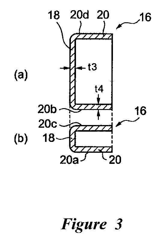
[0011]The bottom section and the side section preferably are integrally formed from a single plate material so that the tubular product can be easily manufactured and so that any leakage between the bottom section and the side section of the tubular product can be minimized. Further, the thickness of the plate of material (e.g., the thickness of the plate of the bottom section) can be arbitrary. The thickness of other portions of the plate material (e.g., the thickness of the portion of the plate used to form the side section) can affect the length of the tubular product.
[0012]The strength and rigidity of the tubular product also can be improved by forming projecting sections along or on a portion of the side section. The projecting sections preferably project outward on at least one outer surface among the four outer surfaces of the side section. A large number of projecting sections can be provided to a portion that requires added strength.

Problems solved by technology

The outer surface of the side section is not scratched by a die or any other machining tool as in a conventional manner, which results in a side section that is not easily fractured.

Method used


Image

  • Tubular product and manufacturing method and manufacturing device thereof
  • Tubular product and manufacturing method and manufacturing device thereof
  • Tubular product and manufacturing method and manufacturing device thereof

Examples


Embodiment Construction

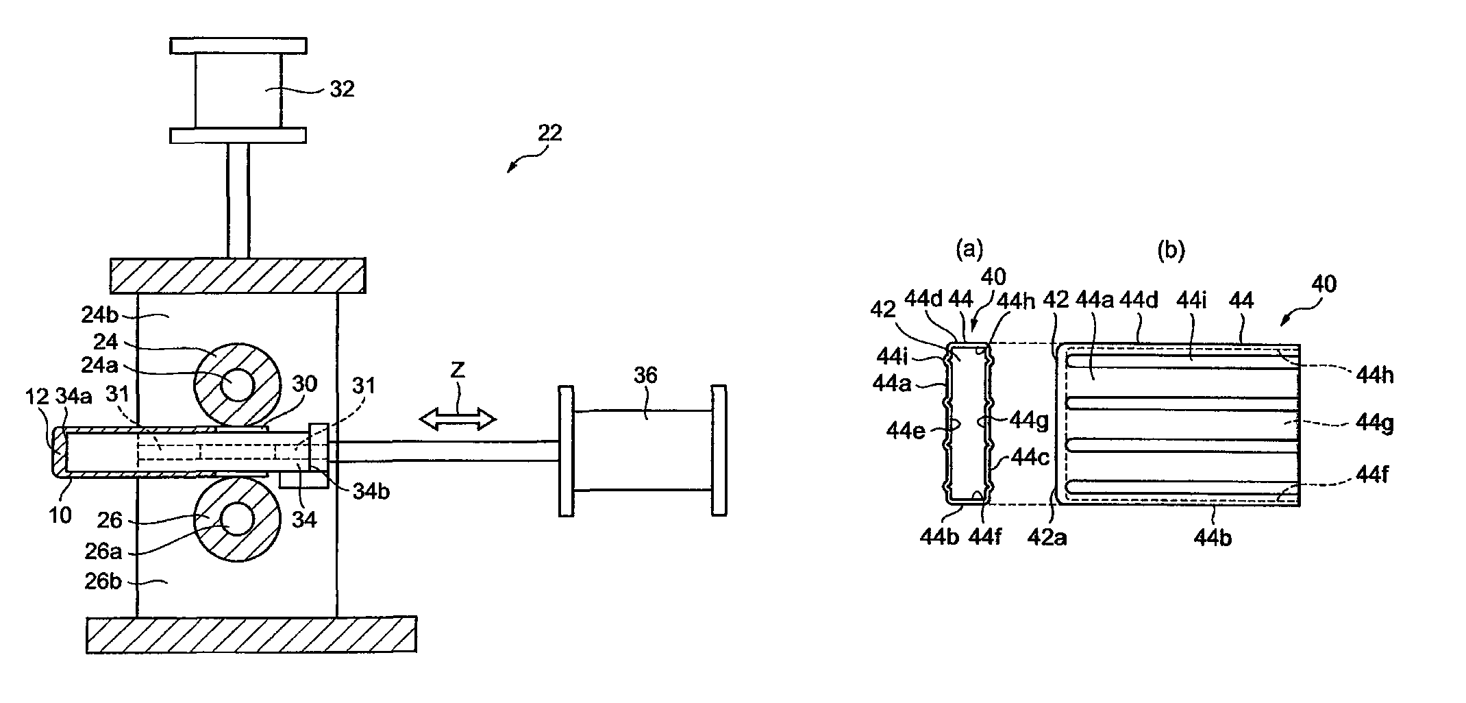
[0027]Tubular products that are arranged and configured in accordance with certain features, aspects and advantages of the present invention comprise a side section having a tubular shape with outer surfaces disposed along a parallelogram and a bottom section formed at one end of the side section. The outer surfaces of the side section preferably are extended by applying pressure with a roller.

[0028]The term“parallelogram” should be interpreted in the broadest sense and is not limited to parallelograms in a strict sense as used in mathematics. For instance, the term “parallelogram” as used herein includes shapes that are substantially parallelograms, such as a parallelogram with round corners, a parallelogram with a partially convex side, a parallelogram with a side projecting along an area, and so forth.

[0029]The phrase “outer surfaces disposed along a parallelogram” means that the outer surfaces may be positioned at least partially along the sides of a parallelogram. The meaning o...


PUM

PropertyMeasurementUnit
thickness t2aaaaaaaaaa
thickness t4aaaaaaaaaa

Abstract

A tubular product comprises a side section having outer surfaces disposed along a parallelogram and a bottom section formed on one end of the side section. The outer surfaces of the side section are pressure formed by a roller. The tubular product preferably is manufactured from a tubular material by a process comprising the use of a device having a roller that is configured to engage with a side section of the tubular material. The device also comprises a mandrel configured to position the tubular material so that the roller can apply pressure against at least a portion of the outer surfaces of the side section and can extend the side section of the tubular material to form the product.

Description

CROSS-REFERENCE TO RELATED APPLICATIONS[0001]This application claims the priority benefit of Japanese Patent Application No. 2007-064854, which was filed on Mar. 14, 2007 and which is hereby incorporated by reference in its entirety.BACKGROUND OF THE INVENTION[0002]1. Field of the Invention[0003]The present invention generally relates to a tubular product, and a device and method for manufacturing the same.[0004]2. Description of the Related Art[0005]Conventionally, a deep drawing or metal spinning process can be used to manufacture a bottomed tubular product. One such conventional manufacturing method is described in JP-A-2001-225134.[0006]These conventional processes and the tubular products that they produce are not without problems. For instance, when a conventional deep drawing process is used to manufacture a tubular product from a material, multiple drawing processes may be required to create the product and the product may develop flange wrinkles in the process. In addition,...

Claims


Application Information

Patent Timeline
Patent Type & Authority Patents(United States)
IPC IPC(8): B21D17/04B21D31/00B21D51/02
CPCB21H7/187Y10T428/12389Y10T428/12382
Inventor KUNIMOTO, YUKITAKASAITO, TOSHIYA
Owner KUNIMOTO IND CO LTD
Why Eureka
Eureka Blog
Learn More