Gas diverter for well and reservoir stimulation

a technology for reservoirs and gas diverters, which is applied in the direction of fluid removal, borehole/well accessories, chemistry apparatuses and processes, etc., can solve the problems of increasing the degree of fracturing within the low stress downhole formation, affecting the health and productivity of wells, and reducing the extent and/or degree of fracturing within the high stress formation, so as to prevent well bashing and/or well interference

Inactive Publication Date: 2019-04-11
HIGHLANDS NATURAL RESOURCES +1
View PDF5 Cites 2 Cited by
  • Summary
  • Abstract
  • Description
  • Claims
  • Application Information

AI Technical Summary

Benefits of technology

[0127]In accordance with some embodiments of the present disclosure is a method for protecting a target well from being fractured that includes injecting a gas into a target wellbore, where the injected gas occupies a target subterranean formation comprising at least about 1 scf / lfCA over a lfCA from about 1 foot to about 15 miles of the target wellbore, and where adjacent to the target wellbore is an interferer wellbore. The interferer wellbore can be one or more of wells scheduled for fracturing, undergoing a fracturing process, or both. Generally, the injected gas occupying the target subterranean formation substantially prevents the fractures generated during the fracturing process of the interferer well from propagating into the target subterranean formation or multiple formations. It can be appreciated that the injected gas occupying the target subterranean formation substantially prevents well bashing and / or well interference. Moreover, the injected gas occupying the target subterranean formation substantially shields and / or protects the target subterranean formation or multiple formations from being fractured by the fracturing system of adjacent interfering wellbores.

Problems solved by technology

More particularly, the process of the present disclosure in relation to current practices can decrease the extent and / or degree of fracturing within the low stress downhole formations and increase the degree of fracturing within the high stress formations.
It can be appreciated that solid particles can be detrimental to well health and productivity.

Method used


Image

  • Gas diverter for well and reservoir stimulation
  • Gas diverter for well and reservoir stimulation
  • Gas diverter for well and reservoir stimulation

Examples


Embodiment Construction

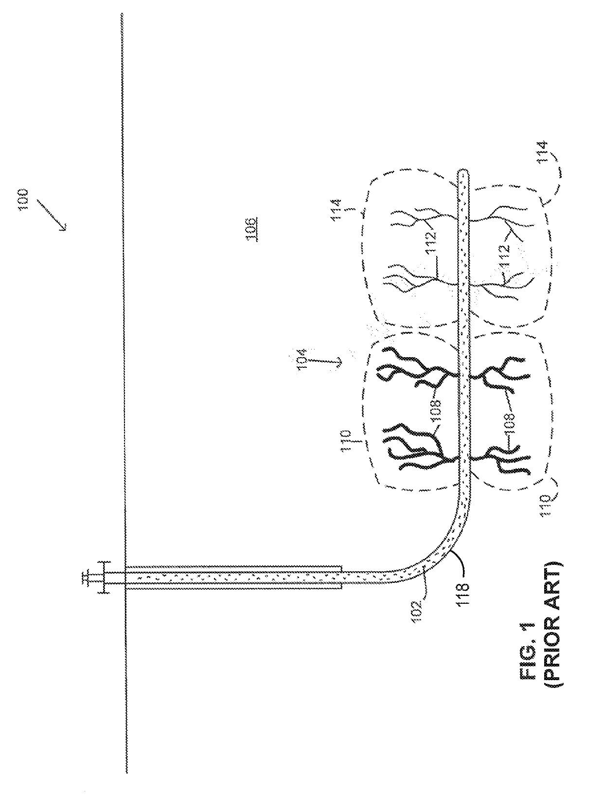
[0177]FIG. 1 depicts a side view of a horizontal drilled well 100 treated according to a method of the prior art utilizing a fracturing liquid 102 to produce multiple fractures 104 within a subterranean formation 106. The multiple fractures 104 produced by the pressurized liquid 102 can vary in size. Typically, low stress zones 110 contain larger fractures and / or pore volumes 108 than high stress zones 114. During stimulation, re-stimulation or re-fracturing the fracturing liquid 102 typically tends to concentrate in the larger fractures and / or larger pore volumes 108 of low stress zones 110. These low stress zones 110 tend to be zones of hydrocarbon depletion, lower pore pressure, higher permeability, or a combination thereof. Permeability of the reservoir can, in part, depend on the extensiveness and interconnectivity of the fractures and / or pores. Moreover, hydrocarbon flow typically depends on the extensiveness and / or interconnectivity of the fractures and / or pores that create p...


PUM


Abstract

The fracturing methods described in the present disclosure provide advantage over the current fracturing methods. The disclosed fracturing methods can change the fracture gradient of the downhole subterranean formation. For example, one or more of the fracture gradients of the low and high stress zones of the downhole subterranean formation can be changed. Furthermore, the methods of present disclosure, in relation to current practices, can decrease the extent and/or degree of fracturing within low stress downhole formations and increase the degree of fracturing within high stress formations.

Description

CROSS-REFERENCE TO RELATED APPLICATIONS[0001]The present application claims priority under 35 U.S.C. § 119 to U.S. Provisional Patent Application No. 62 / 627,138, which was filed Feb. 6, 2018.[0002]The present application is also a continuation-in-part application of and claims priority to U.S. patent application Ser. No. 15 / 870,713, which was filed Jan. 12, 2018.[0003]The present application is also a continuation-in-part application of and claims priority to U.S. patent application Ser. No. 15 / 870,677, which was filed Jan. 12, 2018.[0004]The present application also claims priority under 35 U.S.C. § 119 to U.S. Provisional Patent Application No. 62 / 594,539, which was filed Dec. 4, 2017.[0005]U.S. patent application Ser. Nos. 15 / 870,713 and 15 / 870,677 are continuation applications of and claim priority to U.S. patent application Ser. No. 14 / 957,182, which was filed Dec. 2, 2015.[0006]U.S. patent application Ser. No. 14 / 957,182 claims priority under 35 U.S.C. § 119 to U.S. Provisiona...

Claims


Application Information

Patent Timeline
Patent Type & Authority Applications(United States)
IPC IPC(8): E21B43/26
CPCE21B43/26C09K8/62C09K8/703C09K8/94E21B43/261E21B43/255E21B43/2605C09K8/594
Inventor MENDELL, PAUL E.MILLER, STEPHEN
Owner HIGHLANDS NATURAL RESOURCES
Why Eureka
Try Eureka