Method and Apparatus for Measuring Torque Transmitted by Driven Wheel of a Cycle or the Like Vehicle

a technology of driving wheels and torque, which is applied in the direction of torque measurement, electric digital data processing, instruments, etc., can solve the problems of high signal to noise ratio, high cost of power meters, and inability to transfer from bikes to bikes, etc., and achieves simple and inexpensive use and manufacture.

Active Publication Date: 2012-01-26
LASER SPOKE
View PDF12 Cites 7 Cited by
  • Summary
  • Abstract
  • Description
  • Claims
  • Application Information

AI Technical Summary

Benefits of technology

[0006]The present invention seeks to overcome the problems associated with the prior art by providing a torque monitoring apparatus and, in an embodiment, to give an improved power meter which is universal and allows monitoring of power output produced by riders of different types of human-powered vehicles. Further objects, each being within at least one embodiment of the present invention, provide an improved power meter which is simple and inexpensive to use and manufacture; which is universal, transferable and can be mounted on most common types of bicycles and tandems; which is based on a contactless method; which is accurate and reliable; and which measures an actual power output.
[0010]In an embodiment, said emitter is fixed securely to a hub of said wheel and said detector is mounted on said rim. In this way a simple, transportable, unobtrusive and easily mountable apparatus is provided. Advantageously, a cylindrical lens may be located at an input of said detector to focus said beam onto said detector.
[0011]Preferably, said emitter generates a beam at intervals synchronised with the wheel rotation. In this way, the beam direction can be selected to increase the safety of the apparatus.
[0012]Optionally, the apparatus further comprises one or more optical elements to direct said beam towards said detector. In this way, the distance between the emitter and detector can be increased to further enhance the deviation of the beam and improve the signal to noise ratio. The optical element may comprise a retro-reflector mounted on said rim, to reflect said beam to said detector mounted on said central region. In this arrangement the distance is doubled. Alternatively, the optical elements may comprise a mirror and a prism, wherein said emitter and said detector are located on a stay of said vehicle, said mirror being secured to said hub and said prism being secured to said rim. By mounting the emitter and detector on the seat stay or the chain stay, all electrical components are attached to non-moving elements of the vehicle which allows simple components to be used thereby reducing the cost.
[0013]In an embodiment, the apparatus further comprises a tube, said tube being arranged between said emitter and said detector to substantially contain said beam. In this way the detector, emitter and beam path are not affected by mud or other debris as the vehicle is operated.

Problems solved by technology

As it is produced from precise parts this power meter is expensive and not transferable from bike to bike.
The accuracy of this method is very dependent on correct system installation, which is not straightforward and needs to be performed by skilled personnel.
Since on a majority of bicycles this displacement is very small, the signal to noise ratio produced by this device is high.
This fact makes the data acquisition process unstable and the method unreliable.
Furthermore, using a bike equipped with the perforated hoop may be hazardous for the rider and for other people around.

Method used


Image

  • Method and Apparatus for Measuring Torque Transmitted by Driven Wheel of a Cycle or the Like Vehicle
  • Method and Apparatus for Measuring Torque Transmitted by Driven Wheel of a Cycle or the Like Vehicle
  • Method and Apparatus for Measuring Torque Transmitted by Driven Wheel of a Cycle or the Like Vehicle

Examples


Embodiment Construction

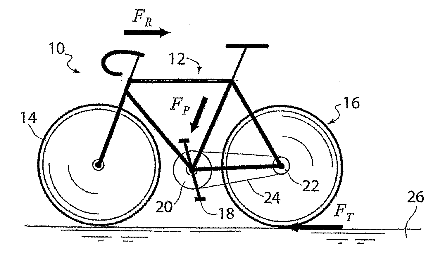
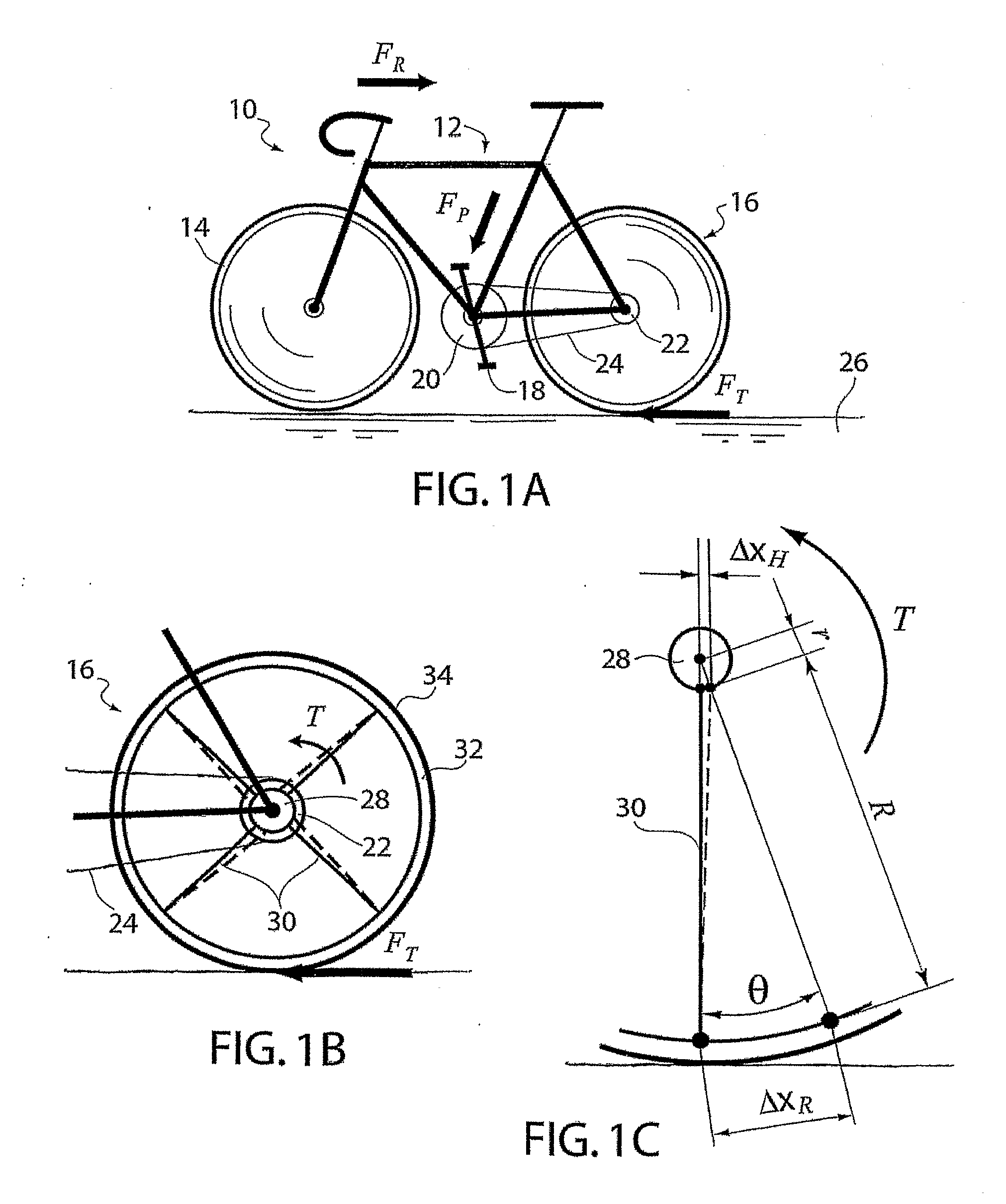
[0027]Embodiments of the present invention will now be described. These embodiments are presented to aid in an understanding of the invention and are not intended to, and should not be construed to, limit the invention in any way. All alternatives, modifications and equivalents that may become obvious to those of ordinary skill upon a reading of the present disclosure are included within the spirit and scope of the invention. FIG. 1A illustrates a typical bicycle 10 which is well known in the art. The bicycle comprised a frame 12, a front wheel 14 and a rear wheel 16, pedals 18, a front sprocket 20 and a rear sprocket 22 connected with a chain 24.

[0028]As well known in the art, to propel bicycle 10, the rider applies force FP to pedals and produces the traction force FT in the contact between the rear wheel 16 and the ground 26 to overcome a sum of aerodynamic, inertia, resistance and gravitational forces operating along the longitudinal direction FR. Force FP transmits, with finite...


PUM

PropertyMeasurementUnit
angleaaaaaaaaaa
angleaaaaaaaaaa
torqueaaaaaaaaaa

Abstract

There is provided an apparatus and method for measuring and monitoring the torque exerted by a cyclist during pedaling of a human-powered vehicle, as for example a bicycle, including an electromagnetic emitter which is adapted to be fixed securely to a rear wheel hub, for generating and directing a beam of electromagnetic radiation towards a rim of the wheel, and a detector mounted on the wheel for detecting the movement of the beam when torque is applied to the wheel, the movement being indicative of an angular displacement of the hub with respect to the rim and directly proportional to the torque. Either alone or using optical elements, the beam is directed to travel at least a distance between the emitter and the rim before detection. The measurement can be used to provide a power output.

Description

FIELD OF THE INVENTION[0001]This invention generally relates to measurement of the torque transmitted by a driving wheel and in particular, though not exclusively, by the driving wheel of a cycle.BACKGROUND OF THE INVENTION[0002]Mechanical power produced by human powered transport is a parameter that reflects both the rider performance and the efficiency of the propulsion system. Monitoring of power output while cycling can help to maintain comfortable and sustainable pedaling over long periods of time. Knowledge of power produced by a rider is very important for people commuting by bike to their work or study and also for those performing fitness exercises. In modern training programmes power measurement is the ultimate tool routinely used by professional coaches to examine performance of elite-level cyclists.[0003]In order to perform power monitoring the vehicle e.g. bicycle, should be equipped with a portable system able to acquire, to calculate and to display data throughout the...

Claims


Application Information

Patent Timeline
Patent Type & Authority Applications(United States)
IPC IPC(8): G01L3/14G06F19/00
CPCG01L3/242G01L3/1421
Inventor LUBARSKY, GENNADY
Owner LASER SPOKE
Why Eureka
Try Eureka