
Advanced peak ballast
A technology of ballast and pinnacle, which is applied in the field of advanced pinnacle ballast, which can solve the problems of increasing copper resistance, unfavorable energy saving, large magnetic loss, etc.
Patent Information
- Authority / Receiving Office
- CN · China
- Patent Type
- Applications(China)
- Current Assignee / Owner
- Publication Date
- 2014-03-26
- Estimated Expiration
- Not applicable · inactive patent
Smart Images
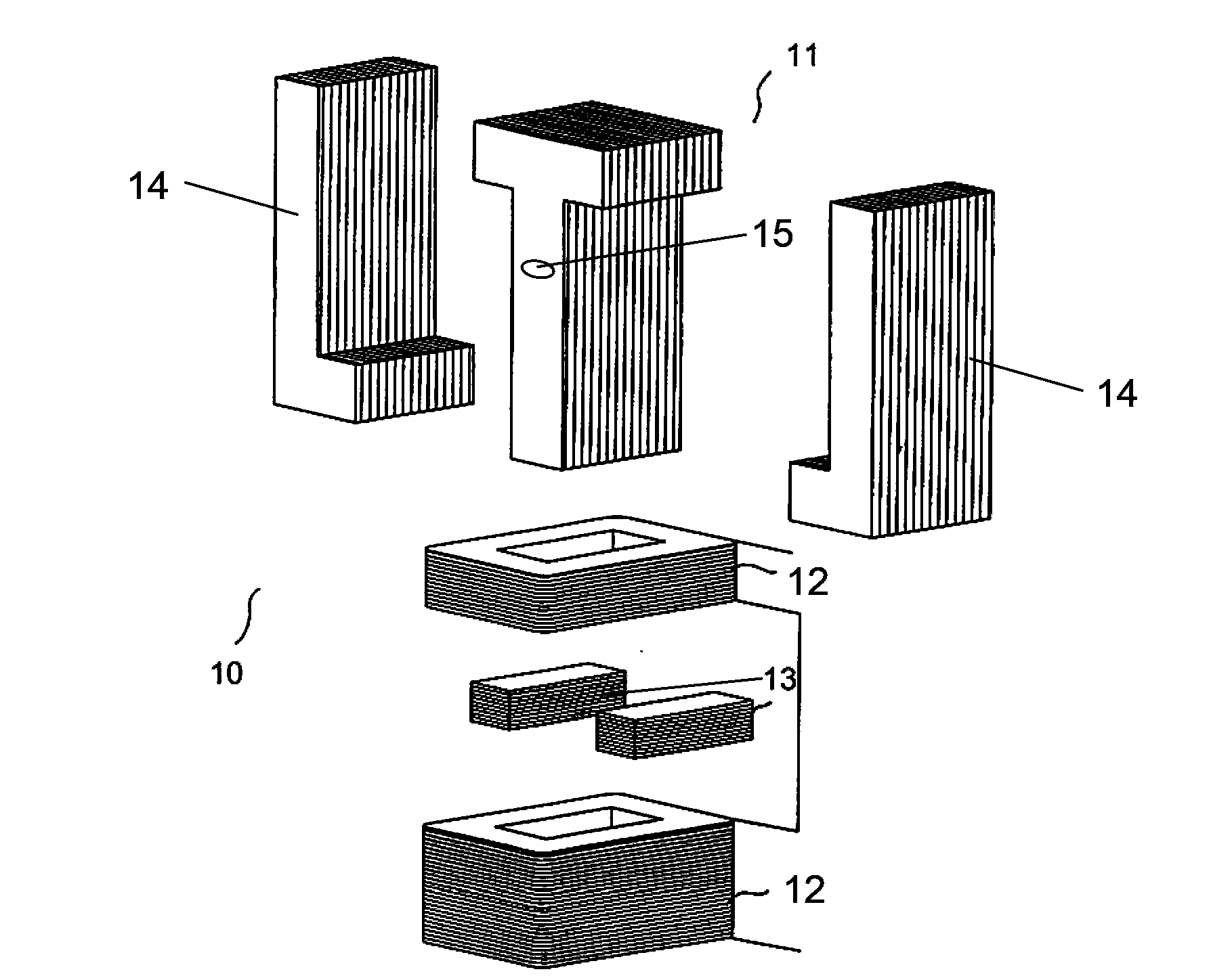
Figure 1 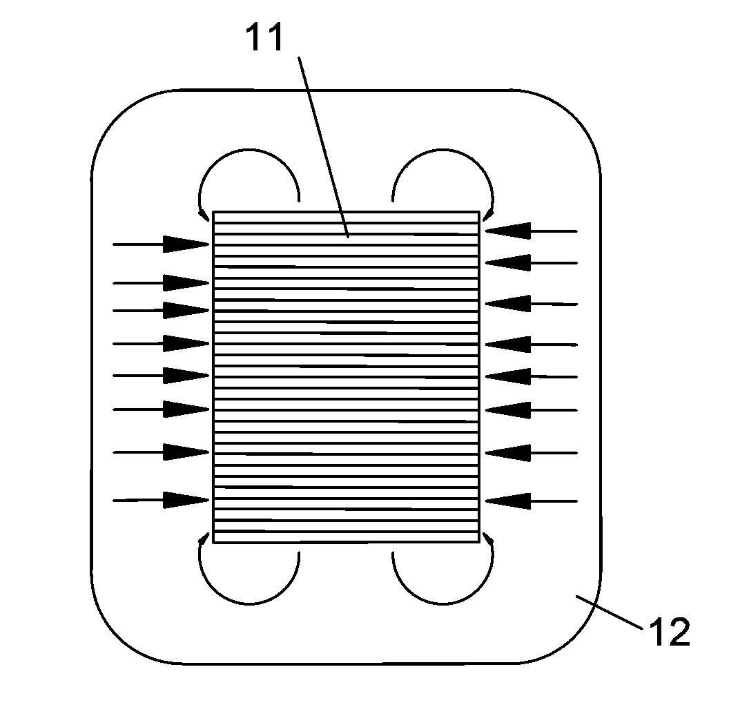
Figure 2 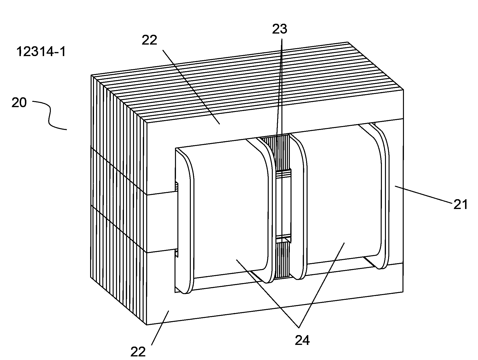
Figure 3
Abstract
Description
technical field
[0001] This invention relates to ballasts, and more particularly, to a leading peak ballast. Background technique
[0002] The structure of the traditional leading peak ballast 10 is as follows figure 1 As shown, it includes T-shaped core post 11, L-shaped magnetic yoke 14, inline magnetic shunt block 13 and wire package 12, T-shaped core post 11 has flux leakage holes 15, and two L-shaped magnetic yokes 14 are arranged symmetrically. On both sides of the core column and spliced with it, the two magnetic shunt blocks 13 are respectively arranged horizontally in the two spaces formed by splicing the T-shaped core column 11 and the L-shaped magnetic yoke 14, and the wire packages 12 are placed on the core column respectively, and are connected by Magnetic shunt blocks 13 are separated. In addition, the T-shaped core column 11, the L-shaped magnetic yoke 14, and the inline magnetic shunt block 13 are all formed by stacking silicon steel sheets of correspondi...
Examples
Embodiment Construction
[0016] The technical solutions of the present invention will be further described below in conjunction with the accompanying drawings and embodiments.
[0017] see image 3 , Figure 4 As shown, the leading peak ballast 20 of the present invention is similar to the prior art, and also includes a core post 21, an L-shaped magnetic yoke 22, an inline magnetic shunt block 23 and a wire package 24. The difference is that the The stem 21 includes a T-shaped main stem 211 with a magnetic flux leakage hole 25 and a trapezoidal auxiliary stem 212 that is separately arranged on both sides of the main stem 211 and integrally formed with it. Two L-shaped yokes 22 are symmetrically arranged on the stem 21. Two magnetic shunt blocks 23 are arranged horizontally in the two spaces formed by the splicing of the core post 21 and the L-shaped yoke 22. Road blocks 23 apart. Wherein, the entire core column 21 is formed by stacking T-shaped silicon steel sheets, and the width of the T-shaped si...