
Microactuator arrangement for deflecting electromagnetic radiation
A technology of micro-actuator and electromagnetic radiation, which is applied in installation, instrumentation, optics, etc., to achieve the effects of space saving, compactness, cheap manufacturing, and large deflection angle
Patent Information
- Authority / Receiving Office
- CN · China
- Patent Type
- Applications(China)
- Current Assignee / Owner
- Publication Date
- 2014-10-15
- Estimated Expiration
- Not applicable · inactive patent
Smart Images
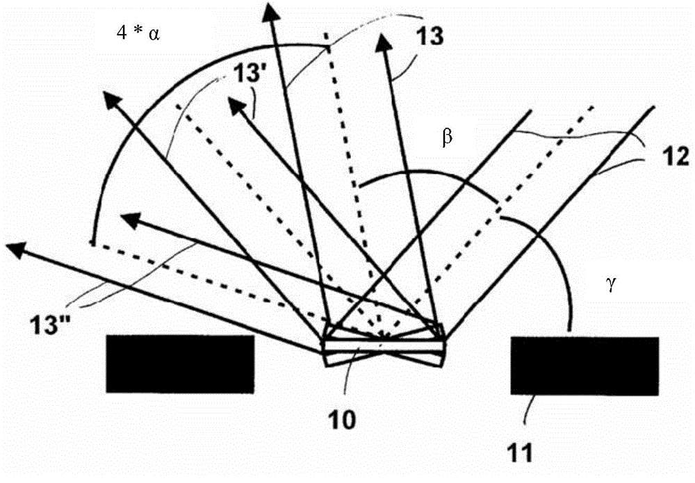
Figure 1 
Figure 2 
Figure 3
Abstract
Description
technical field
[0001] The invention relates to a microactuator arrangement for deflecting electromagnetic radiation according to the preambles of the independent claims. Background technique
[0002] Resonantly operated micromirror actuators (MEMS scanners) are generally known in the art. It is commonly used to deflect laser light or other electromagnetic radiation. Micromirror actuators can be understood as mirrors fabricated with microtechnology that are movably suspended on torsion springs and / or bending springs and set in motion by electrostatic, electromagnetic, thermal or piezoelectric actuation. Resonant operation, achieved by matching the activation frequency to the natural frequency of the actuator, allows the mirror to achieve very large oscillation amplitudes, sometimes greater than + / -30 degrees.
[0003] In most cases, MEMS scanners are applied so that the incident beam always forms an angle > 0 with respect to the deflected beam. This is achieved by angl...
Examples
Embodiment Construction
[0047] figure 1 Schematic representation of a microactuator designed as a scanner with a mirror plate 10 in different pivot positions, a chip frame 11 surrounding the mirror, and the indicated incident beam bundle 12 and mirror plate in different positions Several deflected beam bundles 13, 13', 13''. The beam entry angle or incident angle of the beam bundle 12, i.e. the angle between the mirror surface in the idling position and the incident or outgoing beam is denoted as "γ", and the smallest angle between the incident beam 12 and the scanning outgoing beam is designated as "β ”, where the angle realizes the spatial separation of the incident beam and the scanning angle region given by the oscillating mirror, and the angle “α” is the amplitude of the mechanical oscillation of the mirror 10. As mentioned in the introductory part of this specification, this figure is used to illustrate the expected scanning angles of MEMS scanners.
[0048] The microactuator device accordin...