
Shunting type discarding flow filter device
A waste flow filtration and split flow technology, which is applied in water supply equipment, grease/oily substance/suspended matter removal devices, water/sludge/sewage treatment, etc., can solve the problems of troublesome sediment removal and high cost of use, and achieve low cost Low, reduced impact, easy to clean the effect
Patent Information
- Authority / Receiving Office
- CN · China
- Patent Type
- Applications(China)
- Current Assignee / Owner
- Publication Date
- 2014-12-03
- Estimated Expiration
- Not applicable · inactive patent
Smart Images
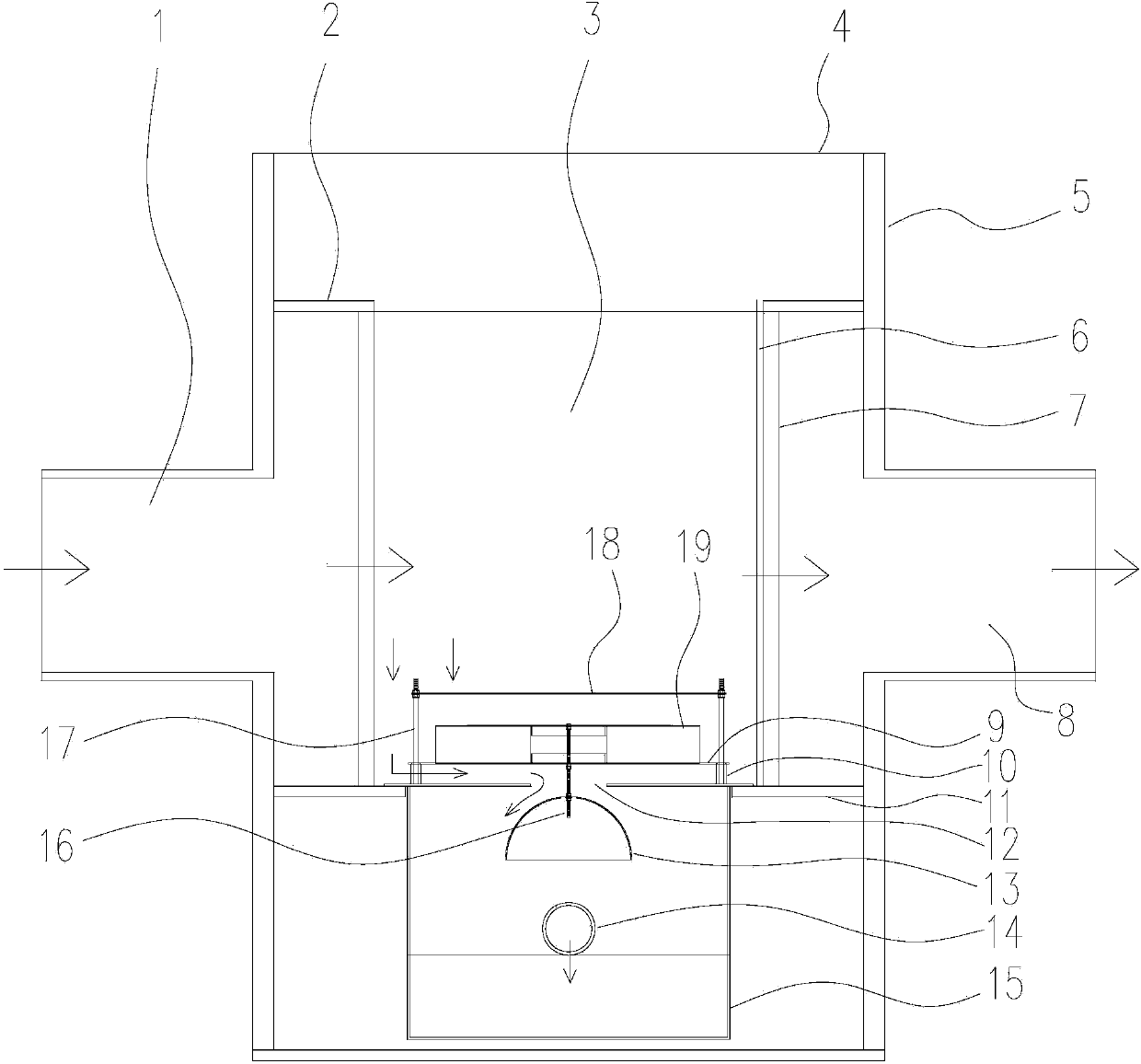
Figure 1 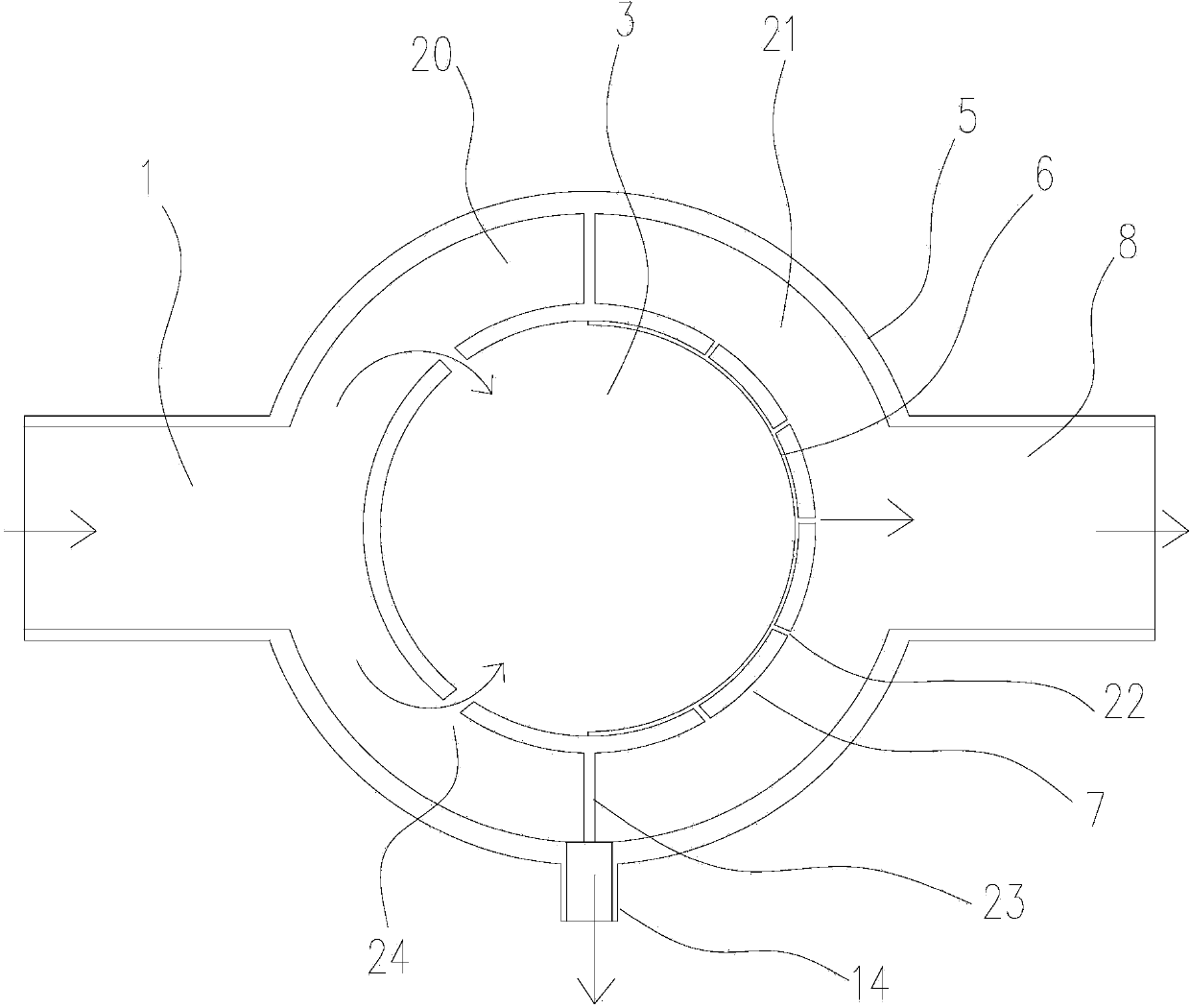
Figure 2
Abstract
Description
technical field
[0001] The invention relates to a rainwater filter device, in particular to a split flow discarded flow filter device. Background technique
[0002] During the falling process of rainwater, dissolved gases, dissolved or suspended solids, heavy metals and bacteria in the air will enter into it. The pollutants in the surface runoff mainly come from the erosion of the surface by rainfall, so the surface sediment is the pollution in the surface runoff. The composition of surface sediments determines the nature of surface runoff pollution. Surface sediments include many pollutants, including solid waste debris (municipal waste, animal manure, accumulations at urban construction sites), chemicals (fertilizers and pesticides applied to lawns), vehicle emissions, etc. The surface with different land use functions The origin of its deposits varies. Therefore, the quality of rainwater varies with location and time. However, with the continuous development of urbaniz...
Examples
Embodiment 1
[0020] Such as figure 1 and figure 2 A shunt type discarding filter device shown includes an outer cylinder 5, an inner cylinder 7, a hanging cylinder 15 and a float valve 19, and the inner cylinder 7 is welded and fixed on the inner wall of the outer cylinder 5 through the upper partition 2 and the lower partition 11 , the upper partition 2 can prevent unfiltered rainwater from overflowing into the outer cavity, the lower partition 11 can place the hanging tube 15, the inner tube 7 and the outer tube 5 can be made of plastic materials, such as PE plastic or UPVC plastic, and the outer tube The two sides of 5 are provided with water inlet 1 and water outlet 8, and the water inlet 1 and water outlet 8 are connected with the outer cylinder 5 in a detachable manner such as threaded way, and the water inlet is connected to the sewage interception equipment, and the rainwater passes through the sewage interception equipment. The water inlet enters, and the water outlet 8 is conne...
Embodiment 2
[0023]The difference between this embodiment and Embodiment 1 is that the top of the stabilizing bar 17 is fixed with a steady flow plate 18, and the steady flow plate 18 is located above the float valve 19, the two are not in direct contact, the steady flow plate can be circular or For other shapes, as long as it is not smaller than the float valve, the rainwater falling down from both sides will not directly hit the light float valve below, effectively stabilizing the float valve.