
Electronic circuit capable of performing wireless charging/discharging and receiving/transmitting communication signals, and equipment
A communication signal and electronic circuit technology, applied in the field of electricity, can solve the problems of high cost, high price, short life, etc.
Patent Information
- Authority / Receiving Office
- CN · China
- Patent Type
- Applications(China)
- Current Assignee / Owner
- Publication Date
- 2016-01-13
- Estimated Expiration
- Not applicable · inactive patent
Smart Images
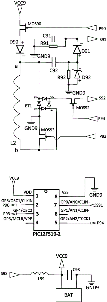
Figure 1 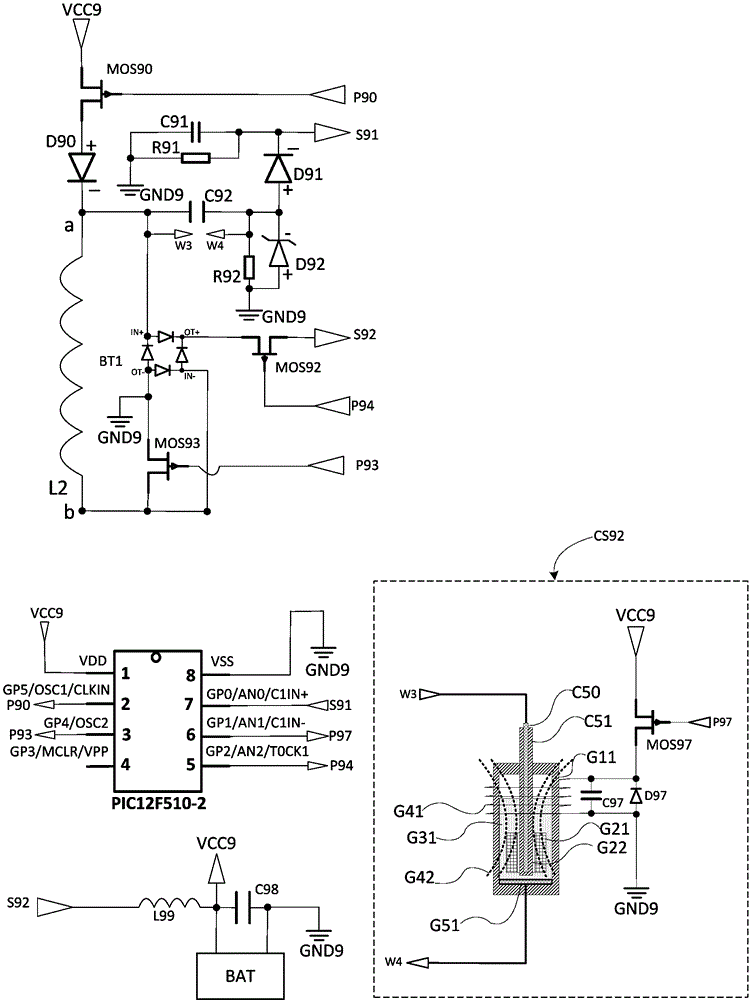
Figure 2 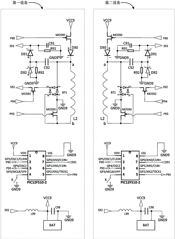
Figure 3
Abstract
Description
technical field
[0001] The invention belongs to the field of electricity, and relates to an electronic circuit and equipment capable of wireless charging and discharging and sending and receiving communication signals. Background technique
[0002] Wireless charging technology is a technology that utilizes magnetic resonance, electromagnetic resonance or electromagnetic induction to realize power transmission without wires; the cost of wireless charging products in the prior art is high and there is room for reduction; the wireless charging products in the prior art can realize There are very few products that transmit power between devices with batteries (that is, devices that can be powered by their own rechargeable batteries), and products that can transmit power between devices with batteries and transmit information through their coils Fewer, there is a need for further development.
[0003] The cost of existing wireless charging products is very high, especially the p...
Examples
Embodiment 1
[0091] Implementation example 1, such as figure 1 , an electronic circuit capable of wireless charging and discharging and capable of sending and receiving communication signals, characterized in that it includes a transmitting switch MOS90, a protection diode D90, a high-pass filter capacitor C92, a redundant resistor R92, a voltage regulator tube D92, and a half-wave rectifier diode D91 , sampling resistor R91, sampling capacitor C91, rectifier bridge BT1, power receiving switch MOS92, power receiving control point P94, switching switch MOS93, coil L2, power point VCC9, location GND9, emission control point P90, power receiving point S92, switching control Point P93, sampling output point S91, microcontroller PIC12F510-2, rechargeable battery BAT, low-pass filter inductor L99, power output capacitor C98;
[0092] The emission switch MOS90 has a controlled channel and a control terminal. When the level of the control point of the emission switch MOS90 is high, the controlled ...
Embodiment 2
[0115] Implementation example 2, such as figure 2 As shown, an electronic circuit capable of wireless charging and discharging and capable of sending and receiving communication signals is characterized in that it includes a transmitting switch MOS90, a protection diode D90, a high-pass filter capacitor C92, a redundant resistor R92, a voltage regulator tube D92, and a half-wave rectifier Diode D91, sampling resistor R91, sampling capacitor C91, rectifier bridge BT1, power receiving switch MOS92, power receiving control point P94, switch MOS93, coil L2, power point VCC9, location GND9, emission control point P90, power receiving point S92, Switching control point P93, sampling output point S91, microcontroller PIC12F510-2, rechargeable battery BAT, low-pass filter inductor L99, power output capacitor C98, controllable capacitor CS92;
[0116] The emission switch MOS90 has a controlled channel and a control terminal. When the level of the control point of the emission switch M...
Embodiment 3
[0151] Implementation example 3, an electronic circuit capable of wireless charging and discharging as described in implementation example 2 and capable of sending and receiving communication signals, characterized in that: the bottom electrode G51 of the controllable capacitor CS92 and the second controlled channel of the controllable capacitor CS92 There is also a ball switch in series between points W4 to prevent capacitors from being used if they are placed incorrectly.