
Electrolyte tubular reactor and reaction method
A tubular reactor and electrolyte technology, applied in the chemical industry, can solve the problems of high energy consumption, long time, low efficiency, etc., and achieve the effects of wide quality range, small batch and short process time
Patent Information
- Authority / Receiving Office
- CN · China
- Patent Type
- Applications(China)
- Current Assignee / Owner
- Publication Date
- 2017-02-08
Smart Images
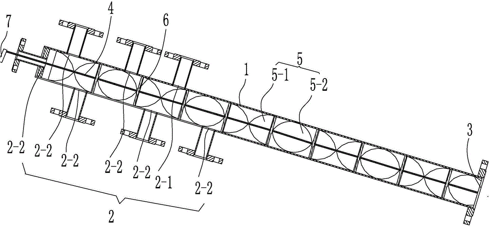
Figure 1 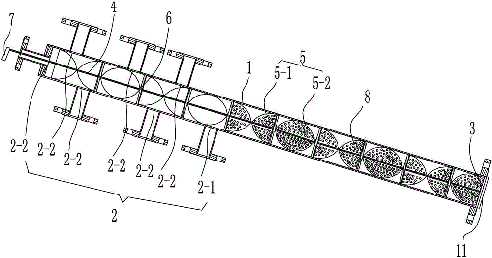
Figure 2 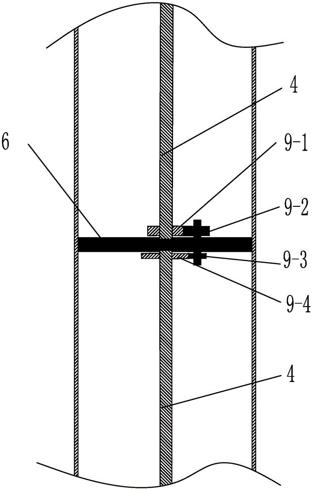
Figure 3
Abstract
Description
technical field
[0001] The invention relates to the technical field of chemical industry, in particular to an electrolyte tubular reactor and a reaction method. Background technique
[0002] When a large amount of production is required for the production of electrolyte using the current reactor, multiple batches and multiple reactors are often required for production, and continuous production of feeding, stirring, and discharging cannot be realized. Only the first feed, then stirring, and then stirring for a period of time Discharge. Using a specific reactor, a reactor can only produce specific mass parts of electrolyte. And the use of existing reactors has relatively serious residual problems.
[0003] The solvents of lithium-ion battery electrolytes currently on the market include DMC (dimethyl carbonate), DEC (diethyl carbonate), EMC (ethyl methyl carbonate), EC (ethylene carbonate), etc., EC is in each formula A substance that will always be contained in the system,...
Examples
specific Embodiment approach
[0031] An electrolyte tubular reactor, characterized in that: it includes a reaction tube body 1 with a reaction cavity inside, the tube body of the reaction tube body 1 is arranged with one end high and one end low, and the reaction tube body 1 is at a height One end is provided with a plurality of raw material inlets 2 for adding different electrolytes to prepare raw materials, and the lower end is provided with a discharge port 3 for discharging electrolytes;
[0032] In the cavity of the reaction tube body 1, along the axial direction of the reaction tube body 1, a plurality of rotating shaft segments 4 rotating around the same axis line are sequentially arranged, and the rotational speeds and / or steering directions of two adjacent rotating shaft segments 4 are different from each other The cavity of the reaction tube body 1 is also provided with a transmission device between two adjacent rotating shaft segments 4 to make the rotational speed and / or steering of the adjacent...
Embodiment 1
[0047] Such as figure 1 As shown, an electrolyte tubular reactor is characterized in that: it includes a reaction tube body 1 with a reaction cavity inside, and the tube body of the reaction tube body 1 is arranged with one end high and one end low, and the reaction tube body 1 The high end is provided with a plurality of raw material inlets 2 for adding different electrolytes to prepare raw materials, and the low end is provided with a discharge port 3 for discharging the electrolyte;
[0048] In the cavity of the reaction tube body 1, along the axial direction of the reaction tube body 1, a plurality of rotating shaft segments 4 rotating around the same axis line are sequentially arranged, and the rotational speeds and / or steering directions of two adjacent rotating shaft segments 4 are different from each other The cavity of the reaction tube body 1 is also provided with a transmission device between two adjacent rotating shaft segments 4 to make the rotational speed and / or...
Embodiment 2
[0054] Such as figure 2 As shown, different from the above embodiment, in order to make EC not easy to freeze, at least one raw material feeding port 2 is the EC feeding port 2-1 for connecting with the EC raw material supply device, and the remaining raw material feeding ports Port 2 is other raw material feed port 2-2 for connecting with other electrolyte preparation raw material supply devices; the connection position between EC feed port 2-1 and reaction tube body 1 is located at other raw material feed port 2 After -2; and the mixing and stirring plate located after the EC feeding port 2-1 is provided with microholes 8 penetrating the mixing and stirring plate.
[0055] A filter screen 11 is provided in the discharge port 3 .