
A control method for a bidirectional bridge-type modular switched capacitor ac-ac converter
A switched capacitor and bidirectional switch technology, applied in the field of AC-AC converter, can solve the problem of inflexible voltage regulation capability of switched capacitor AC-AC converter, and achieve the effect of safe converter
Patent Information
- Authority / Receiving Office
- CN · China
- Patent Type
- Patents(China)
- Current Assignee / Owner
- Publication Date
- 2019-10-22
Smart Images
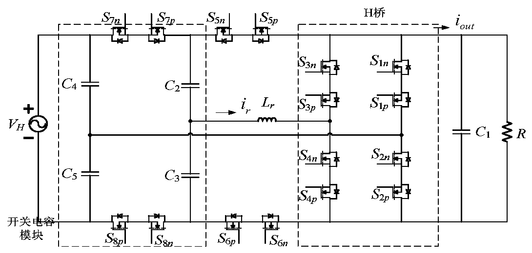
Figure 1 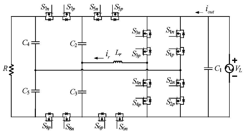
Figure 2 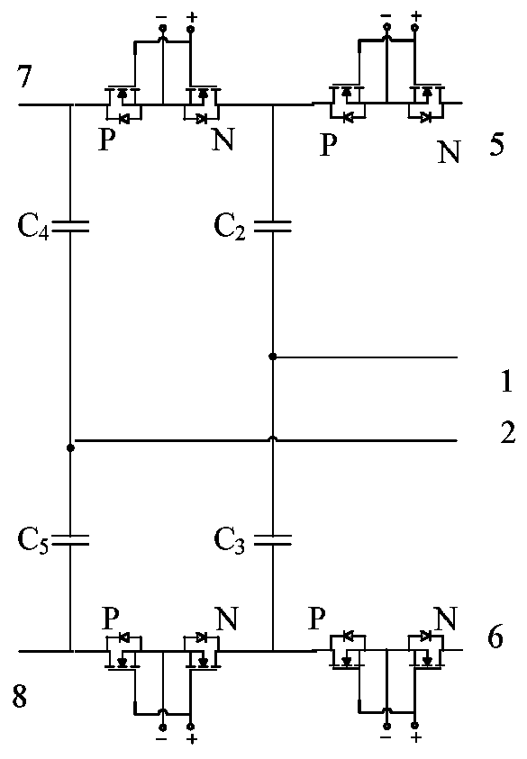
Figure 3
Abstract
Description
technical field
[0001] The invention relates to the technical field of AC-AC conversion, in particular to a control method for a bidirectional bridge-type modular switched capacitor AC-AC converter. Background technique
[0002] Switched capacitor converter is a new type of converter without magnetic components. With its advantages of low cost, small size, high integration, high efficiency and high power density, it is widely used in new energy power generation, micro grid, electric vehicles and other fields. application is becoming more and more widespread. After more than 20 years of development, the switched capacitor converter has made a series of improvements in topology and control methods compared with the first proposed switched capacitor converter, whether it is conversion efficiency or operating power. It has been greatly improved, but most of the existing switched capacitor converters have the disadvantage of weak output voltage ratio adjustment capability. To re...
Examples
Embodiment 1
[0042] This example takes step-down mode as an example: figure 1 As shown, the topology consists of a power supply V H , Basic switched capacitor module, quasi-H bridge, resonant inductor L r , Energy storage capacitor C 1 and load R. The topology shares 16 fully-controlled device MOSFETs, which are numbered as p and n groups respectively. The fully controlled device MOSFET numbered p is S 1p , S 2p , S 3p , S 4p , S 5p , S 6p , S 7p and S 8p , the full-control device MOSFET numbered n is S 1n , S 2n , S 3n , S 4n , S 5n , S 6n , S 7n and S 8n .
[0043] Specifically, such as Figure 4 As shown, the quasi-H-bridge has six input / output terminals, which are named 3, 4, 9, 10, 11, and 12 respectively. The quasi-H bridge includes 8 MOSFET switch tubes S 1p , S 2p , S 3p , S 4p , S 1n , S 2n , S 3n and S 4n , the S 1p and S 1n The common source is connected in series to form the first bidirectional switch, S 2p and S 2n The common source is connecte...
Embodiment 2
[0077] This example takes the boost mode as an example. When the circuit works in the boost mode, the circuit topology remains unchanged, and only the input and output ports need to be exchanged. Such as figure 2 As shown, the topology consists of a power supply V L , Basic switched capacitor module, quasi-H bridge, resonant inductor L r , Energy storage capacitor C 1 and load R. The topology shares 16 fully-controlled device MOSFETs, which are numbered as p and n groups respectively. The fully-controlled device MOSFET numbered in group p is S 1p , S 2p , S 3p , S 4p , S 5p , S 6p , S 7p and S 8p , the full-control device MOSFET numbered n is S 1n , S 2n , S 3n , S 4n , S 5n , S 6n , S 7n and S 8n .
[0078] Specifically, such as Figure 4 As shown, the quasi-H-bridge has six input / output terminals, which are named 3, 4, 9, 10, 11, and 12 respectively. The quasi-H bridge includes 8 MOSFET switch tubes S 1p , S 2p , S 3p , S 4p , S 1n , S 2n , S 3n...