
Trigger switch
A technology for triggering switches and contacts, applied in electrical switches, electrical components, circuits, etc., can solve the problem of not fundamentally solving contact sparks and reducing contact contact sparks.
Patent Information
- Authority / Receiving Office
- CN · China
- Patent Type
- Applications(China)
- Current Assignee / Owner
- Publication Date
- 2017-11-07
- Estimated Expiration
- Not applicable · inactive patent
Smart Images
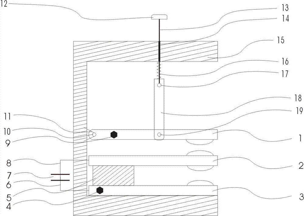
Figure 1 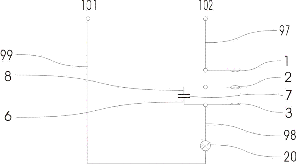
Figure 2
Abstract
Description
technical field
[0001] The invention relates to the technical field of jog switches, in particular to a trigger switch. Background technique
[0002] In power control applications, electrical components such as switches and contactors are usually used to control the on-off of the current. The contact resistance of the connected and disconnected contacts increases due to electric sparks. The larger the electric sparks, the easier it is to cause the contact surface Resistance is generated, and this spark even burns out the contacts, causing the circuit to malfunction. The National Patent Office has disclosed the patent CN200810066620 double-contact switch technology, which is essentially a mechanical way to reduce contact sparks, and does not fundamentally solve the cause of contact sparks generated by contact contacts.
[0003] According to the characteristics of the capacitor, the present invention utilizes the voltage-reducing and current-limiting principle of the capacito...
Examples
Embodiment Construction
[0024] Now refer to the attached figure 1 And attached figure 2 , in combination with specific embodiments, the description is as follows: a trigger switch according to the present invention includes a moving contact 1, a pre-closed contact 2, a static contact 3, a static contact terminal 4, an elastic insulating support 5, a capacitor A side lead wire 6, capacitor 7, capacitor B side lead wire 8, movable contact terminal 9, movable contact housing hinge hole 10, hinge bracket 11, button 12, button insulating connecting rod 13, button connecting rod movable hole 14, Housing 15, spring 16, button connecting rod link reaming hole 17, moving contact connecting body 18, moving contact intermediate link reaming hole 19, load 20, lead wire 97 from power supply to moving contact terminal, static contact terminal Lead wire 98 to load B side, lead wire 99 from load A side to power supply, power supply A terminal 101, power supply B terminal 102.
[0025]The housing 15 is C-shaped as...