
Method for acquiring temperature gradient of specimen examination section in wall thickness direction in TGMF (thermal gradient mechanical fatigue) test
A temperature gradient and acquisition method technology, applied in the direction of strength characteristics, measuring devices, instruments, etc., can solve problems such as difficulty in uniform heating, difficulty in temperature measurement of the inner surface of the assessment section, and difficulty in accurately reflecting the surface temperature, so as to achieve enhanced heating capacity, The effect of ensuring uniformity and overcoming difficulties in temperature measurement
Patent Information
- Authority / Receiving Office
- CN · China
- Current Assignee / Owner
- Publication Date
- 2018-09-07
Smart Images
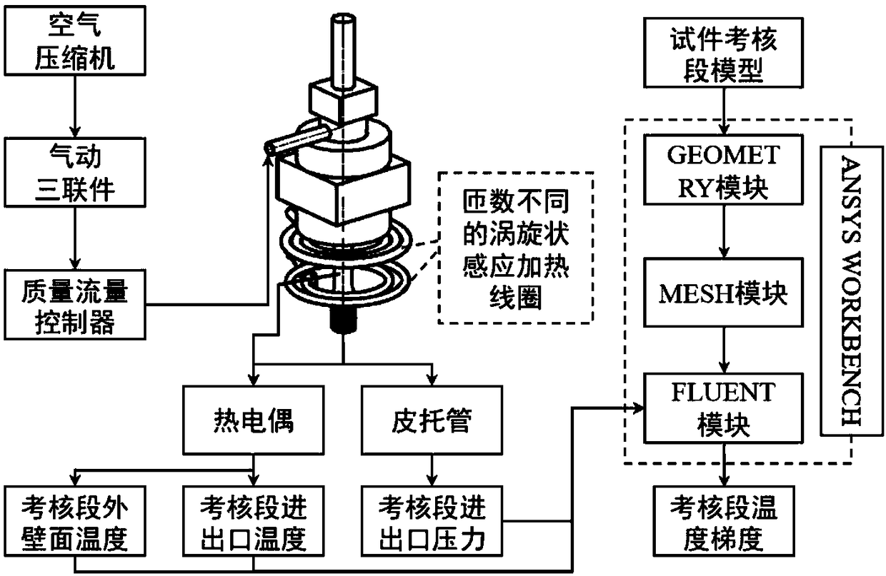
Figure 1 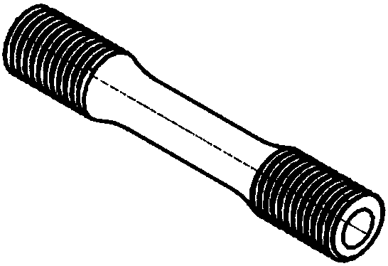
Figure 2 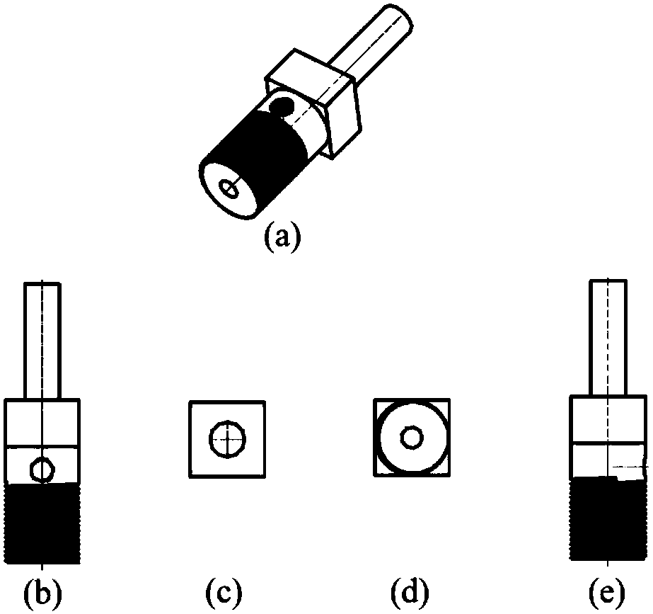
Figure 3
Abstract
Description
technical field
[0001] The invention relates to a method for obtaining the temperature gradient in the wall thickness direction of a test piece in a TGMF test. The TGMF test (i.e. temperature gradient thermomechanical fatigue test) can be used to study the effects of flow and heat exchange process inside a hollow air-cooled turbine blade on thermomechanical fatigue damage It belongs to the field of material high-temperature mechanical property test and aerospace engine technology. Background technique
[0002] Thermomechanical fatigue is the main failure mode of hollow air-cooled turbine blades. Compared with traditional failure modes such as low cycle fatigue, creep and creep-fatigue, thermomechanical fatigue can more accurately describe fatigue, creep, oxidation, etc. Coupling effects of damage factors on turbine blades. With the continuous improvement of the performance of aero-engines, the temperature in front of the turbine is getting higher and higher, and the turbine...
Examples
specific Embodiment approach
[0047] Its specific implementation is as follows;
[0048] first step, such as figure 2 , image 3 , Figure 4 , Figure 5 As shown, the installation of the upper fixture is completed: firstly, respectively screw the hollow circular tube test piece 2 and the chuck 3 with the air flow channel into the adapter 4, and adjust the screwing depth to ensure that the hollow circular tube test piece 2 and the top of the chuck 3 are in contact , clamp the collet 3 on the fatigue testing machine, screw the air nozzle 5 into the collet 3, the assembly condition is as follows Figure 6 As shown, 2, 3, 4, and 5 represent the hollow circular tube test piece, the chuck with air flow channel, the adapter and the gas nozzle respectively.
[0049] In the second step, dry compressed air with constant pressure and mass flow rate is provided through the air compressor, pneumatic triplex, and mass flow controller, and passed into the air nozzle 5 .
[0050] The third step is to make two vortex...