
Vertical shaft multistage board hammer sand making machine
A vertical shaft, sand making machine technology, applied in grain processing, dispersed particle separation, chemical instruments and methods, etc., can solve the problems of inability to hit, small crushing range, etc., achieve fast crushing speed, improve crushing efficiency, and avoid impact Environmental and worker health effects
Patent Information
- Authority / Receiving Office
- CN · China
- Patent Type
- Applications(China)
- Current Assignee / Owner
- Publication Date
- 2019-01-04
- Estimated Expiration
- Not applicable · inactive patent
Smart Images
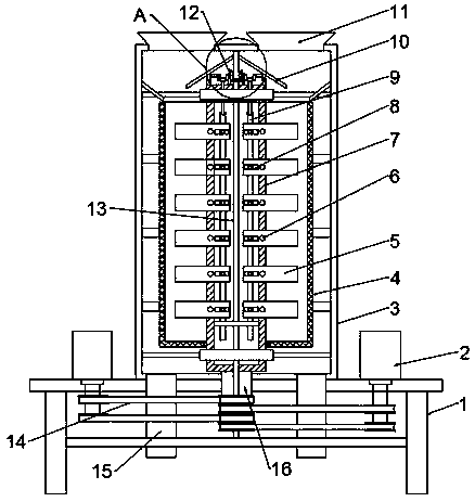
Figure 1 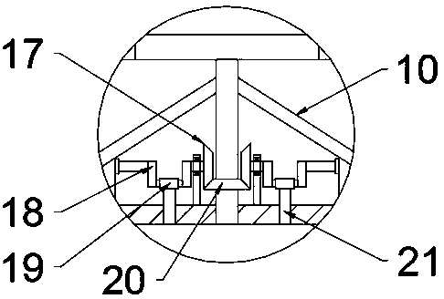
Figure 2 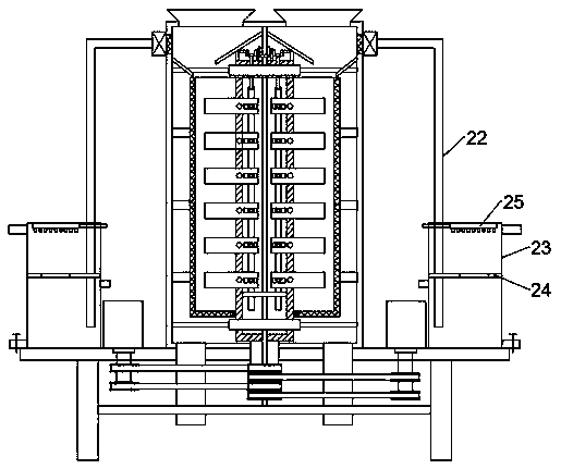
Figure 3
Abstract
Description
technical field
[0001] The invention relates to the technical field of sand making equipment, in particular to a vertical shaft type multi-stage blow bar sand making machine. Background technique
[0002] Natural sand is a non-renewable resource in a short period of time. With the rapid development of my country's infrastructure, natural sand is almost exhausted. At the same time, due to the devastating damage to resources and the environment caused by excavation of sand and gravel, many cities have banned the use of natural sand due to factors such as flood control, environmental protection, and resource protection. Vertical shaft sand making machine is a kind of building material sand making equipment developed in recent years, which can crush rocks, ores or natural pebbles and other stones into industrial sand to replace natural sand.
[0003] Existing vertical shaft crushers mostly adopt a single-layer or two-layer rotor structure, and the blow bars installed on the rot...
Examples
Embodiment 1
[0020] see Figure 1~2 , in an embodiment of the present invention, a vertical shaft multi-stage blow bar sand making machine includes a frame 1, a casing 3, a metal screen cylinder 4, a driving motor 2, a blow bar rotor 7 and a blow bar 5, and the frame 1 is installed with an organic casing 3 through screws, and a metal screen cylinder 4 is concentrically fixed in the casing 3 through a support rod. The top of the metal screen cylinder 4 is open, and the metal screen cylinder 4 is equipped with a blow bar rotor 7, and the bottom of the blow bar rotor 7 is concentric. The hollow shaft 16 is welded and fixed, and the hollow shaft 16 extends to the bottom of the frame 1. On the frame 1, the drive motor 2 is installed on both sides of the casing 3 through bolts. The output shaft of the drive motor 2 is connected to the hollow shaft through the belt transmission member 14. 16 connection, both sides of the top of the casing 3 are provided with feed hoppers 11, both sides of the bot...
Embodiment 2
[0022] see image 3 The difference between this embodiment and Embodiment 1 is that it also includes a dust suction device, which includes a suction fan, a dust removal box 23 and a spray pipe 25, and both sides of the top of the casing 3 are equipped with suction The air pipe 22 is connected to the air outlet of the exhaust fan, and the other end of the air pipe 22 runs through the top of the dust removal box 23 and extends to the bottom of the inner cavity of the dust removal box 23. A partition 24 is fixed in the middle of the inner cavity of the dust removal box 23. Below 24 is a water storage chamber, and air holes are provided on the partition 24. A spray pipe 25 is installed on the top of the dust removal box 23, and a plurality of nozzles are integrated at the bottom of the spray pipe 25, and a water supply pipe is connected to the spray pipe 25. , the exhaust fan extracts the air with a large amount of dust and then passes it into the dust removal box 23 through the a...