
Automatic feeding device for fish farming pond
A technology for fish ponds and equipment, applied in fish farming, climate change adaptation, applications, etc., can solve problems such as motor burnout, user economic loss, fish electrocution, etc., and achieve the effect of avoiding feed blockage
Patent Information
- Authority / Receiving Office
- CN · China
- Current Assignee / Owner
- Publication Date
- 2019-01-08
- Estimated Expiration
- Not applicable · inactive patent
Smart Images
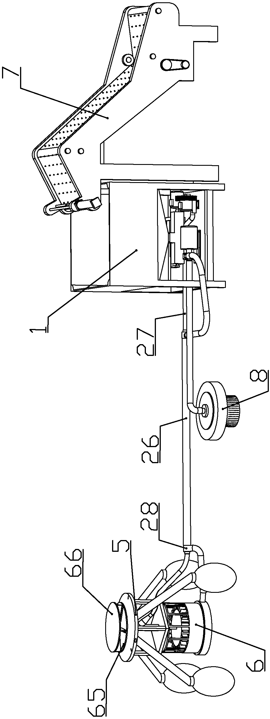
Figure 1 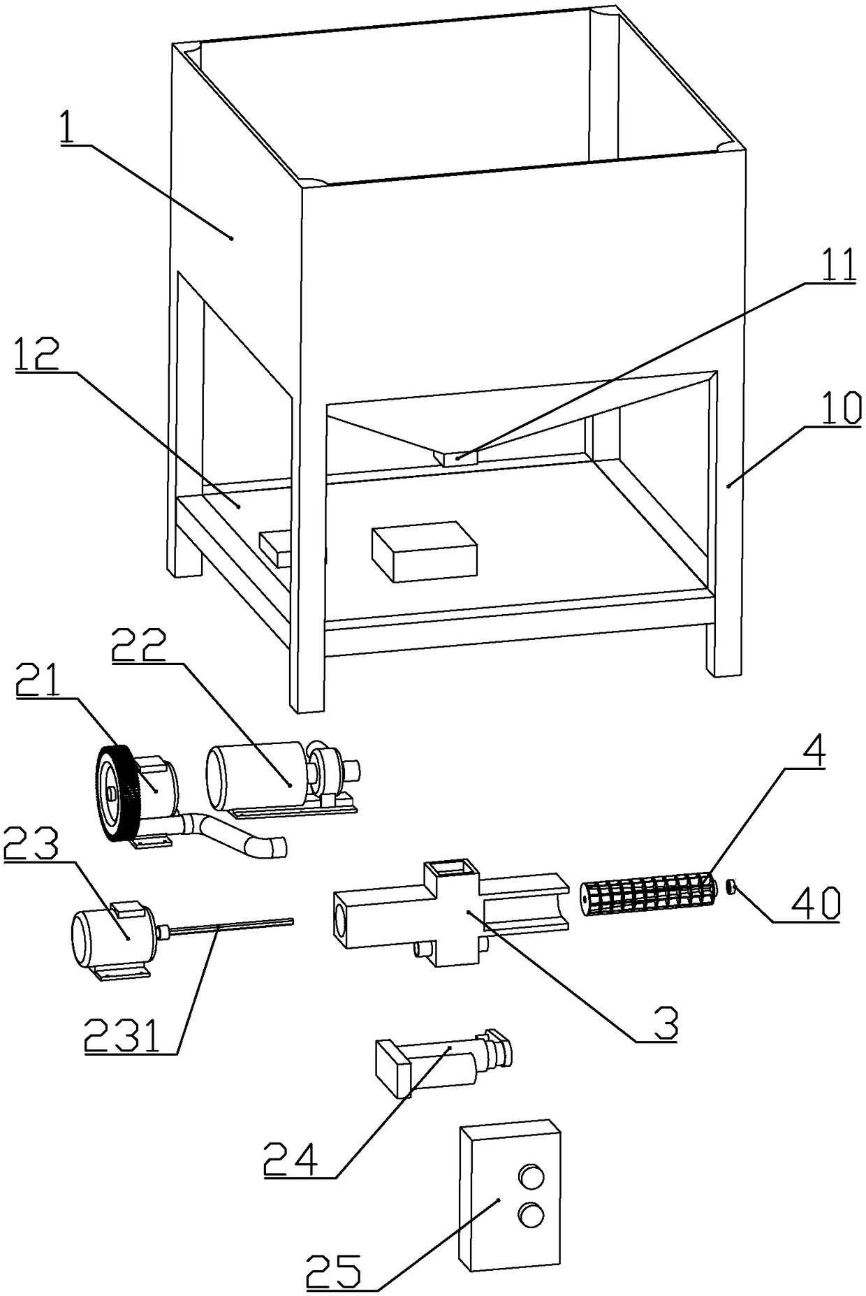
Figure 2 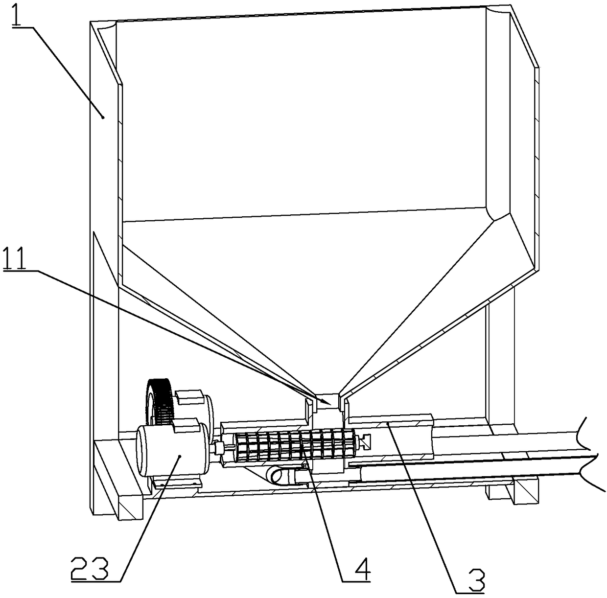
Figure 3
Abstract
Description
technical field
[0001] The invention belongs to the technical field of fishing gear, and in particular relates to automatic bait feeding equipment for aquaculture fish ponds. Background technique
[0002] Document number is that the Chinese patent document of CN203985566U discloses a kind of fishpond automatic feeding device, comprises floating mechanism, throwing material dish, feed pipe, material storage box, blowing mechanism and feeding mechanism, and described throwing material dish is rotatably arranged on On the floating mechanism, one end of the feeding pipe is connected with the throwing tray, the storage box is provided with a feeding port, the blowing mechanism is arranged at the other end of the feeding pipe, and the feeding mechanism includes a feeding cylinder, a feeding Screw and screw driver, the feeding screw is arranged in the feeding barrel, the screw driver is used to drive the feeding screw to rotate, the upper side of the feeding barrel communicates wit...
Examples
Embodiment 1
[0069] according to Figure 1 to Figure 16 As shown, the automatic bait feeding equipment for aquaculture fish ponds described in this embodiment includes a material storage component located in a feed warehouse adjacent to the fish pond, and a throwing component floating on the water surface of the fish pond.
[0070] The material storage assembly includes a bracket 10 and an inverted pyramid-shaped hopper 1 fixedly mounted on the lower end of the bracket. The bottom center of the hopper is formed with a discharge pipe 11; the bracket is located below the hopper and connected with a Bottom plate 12.
[0071] The throwing assembly includes a floating support 5 above the water surface, a plurality of buoys connected to the floating support through connecting rods, a lower bottom plate 52 fixedly connected to the lower end of the floating support, and rotatably connected to the upper end of the floating support for The feed is thrown into the throwing tray in the fish pond; eac...
Embodiment 2
[0111] combine Figure 17 to Figure 19 As shown, this embodiment makes the following improvements on the basis of Embodiment 1: it also includes a material transport assembly 7 located on one side of the storage assembly; the material transport assembly includes a conveyor belt seat 71, and is installed on the conveyor belt The conveyor belt 72 on the seat; the outer wall of the conveyor belt is evenly fixed with spikes 720, so that after a bag of feed is placed on the conveyor belt, the spikes enter the bag, so that the feed will not slip during transportation. The outer wall of the conveyor belt has no spikes near the two sides.
[0112] The conveyor belt is sequentially composed of a placing part 721 arranged horizontally close to the bottom surface, a feeding part 722 arranged obliquely and extending to the top of the chute, and a feeding part 723 arranged obliquely into the chute.
[0113] The two ends of the inner wall of the conveyor belt on the conveyor belt seat are ...