
An rbcot-buck circuit and method for improving transient response and high stability
A RBCOT-BUCK, high-stability technology, applied in the direction of electrical components, adjusting electrical variables, output power conversion devices, etc., can solve the problems of increasing design complexity and affecting the performance of load transient response, so as to eliminate mutual constraints, Reduce design difficulty and improve performance
Patent Information
- Authority / Receiving Office
- CN · China
- Patent Type
- Patents(China)
- Current Assignee / Owner
- Publication Date
- 2020-06-05
Smart Images
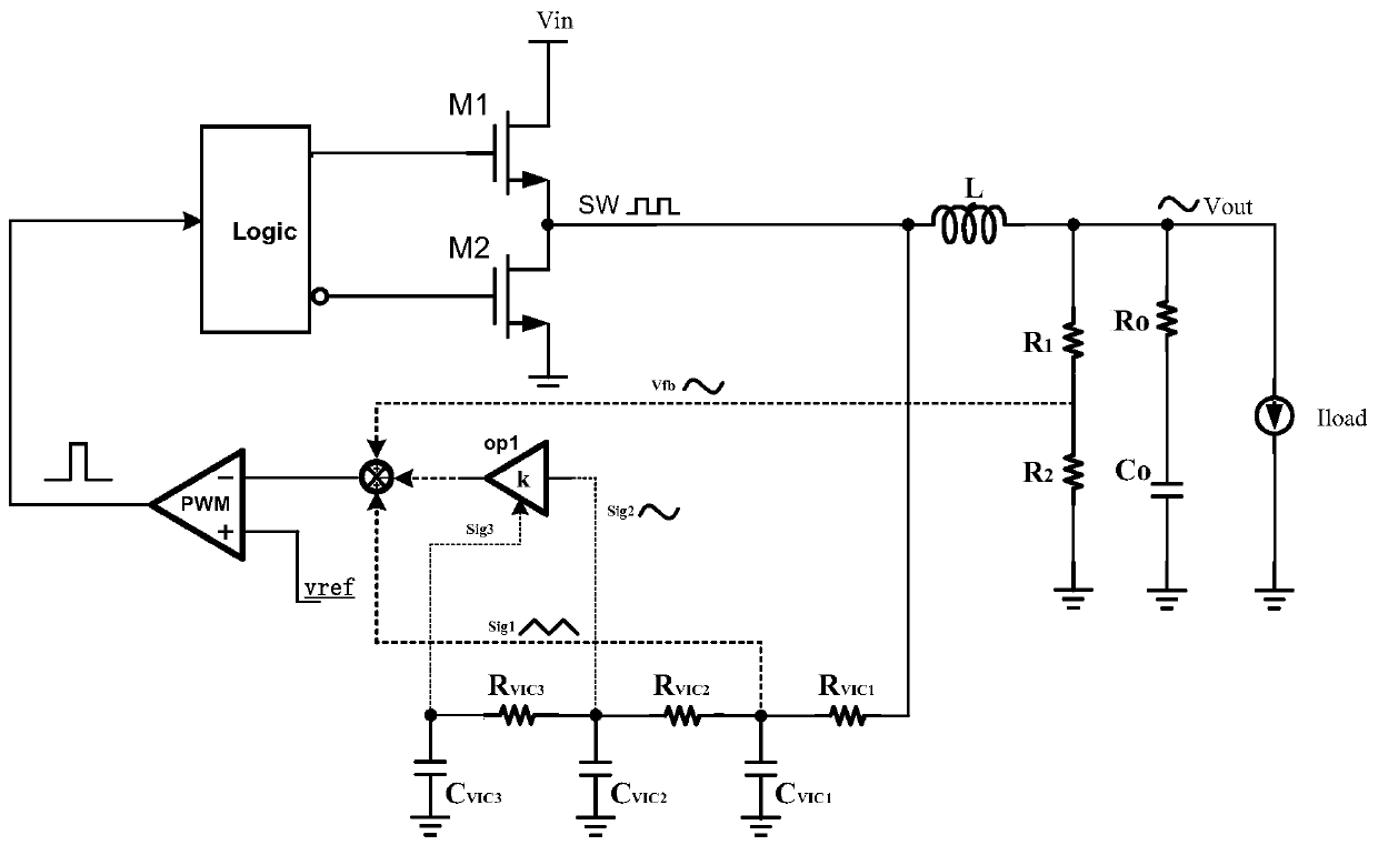
Figure 1 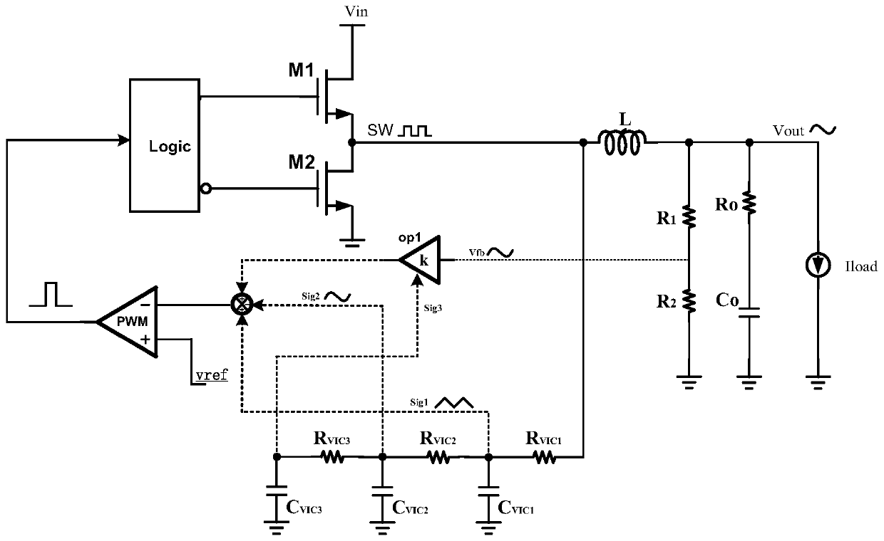
Figure 2 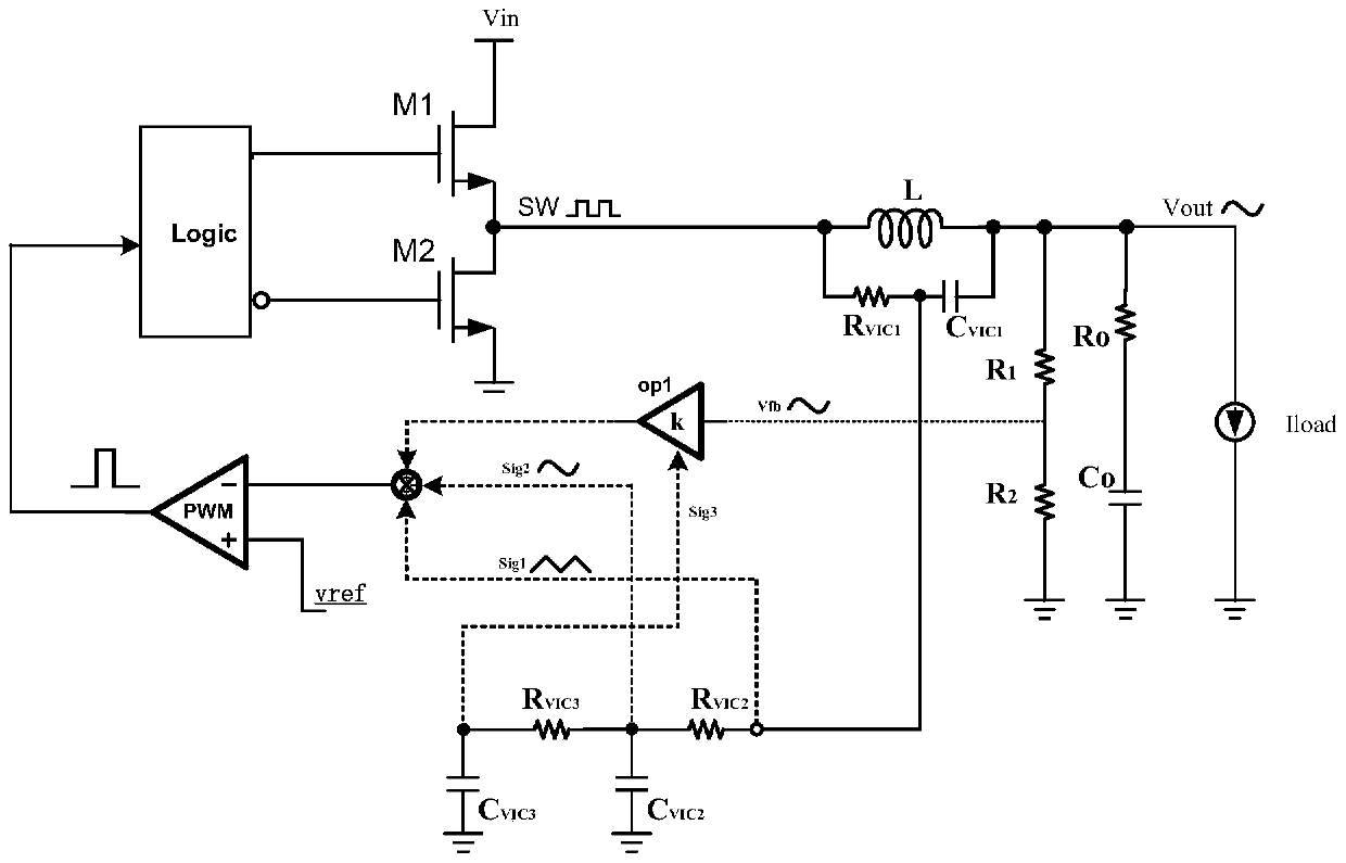
Figure 3
Abstract
Description
technical field
[0001] The invention relates to the technical field of power chips, in particular to an RBCOT-BUCK circuit and method with improved transient response and high stability. Background technique
[0002] The current DC-DC power chip has higher and higher requirements on the load transient characteristics, and it is necessary to maintain the stability of the output voltage under the rapid change of the load. This makes the ripple-based constant on-time (RBCOT) control mode widely used in current buck circuit designs.
[0003] The RBCOT structure controls the switch of the power tube by directly inputting the external voltage feedback signal and the internal reference voltage into the comparator for comparison. The ability to quickly change the switch duty cycle during a load step enables fast load transient response. However, due to the delay of the external voltage feedback signal, it has a great impact on the loop stability in the negative feedback system. I...
Examples
Embodiment 1
[0020] Embodiment 1: To eliminate the output feedback voltage ripple signal and reduce the impact of its delay on the system loop, it is necessary to generate a compensation ripple signal that is opposite in phase to the feedback voltage ripple and has a similar / same amplitude for superimposition, or Generate a compensation ripple with the same phase and similar amplitude as the feedback voltage ripple (the phase delay of the feedback voltage ripple signal will be completely offset when it is the same, and the phase delay of the feedback voltage ripple signal will be partially offset when it is similar) The signal is cancelled. In this embodiment, the compensating ripple signal generating unit (ripple canceling circuit) is arranged in the inner loop of RBCOT, and the output signal of the ripple canceling circuit and the output feedback voltage ripple signal of RBCOT are superimposed and connected to the inner loop of RBCOT . In this way, the entire system loop is completely c...
Embodiment 2
[0021] Embodiment 2: On the basis of Embodiment 1, the ripple cancellation circuit includes a first filter circuit, a second filter circuit, a third filter circuit, an internal ripple amplifier, and the RBCOT external output circuit is provided with a voltage dividing resistor circuit. After the output voltage is divided, the feedback voltage ripple signal is obtained, and the output signal of the SW end of the RBCOT internal loop passes through the first filter circuit, the second filter circuit, and the third filter circuit in sequence, and sequentially generates signal sig1, signal sig2, signal sig3, the first filter circuit is used to generate the signal sig1 as the internal feedback signal of the RBCOT system, the signal sig3 is input to the internal ripple amplifier to control the amplification factor of the internal ripple, and the feedback voltage ripple signal / signal sig2 is combined with the signal sig2 after passing through the amplifier / The feedback voltage ripple...
Embodiment 3
[0040] Embodiment 3: On the basis of Embodiment 1, the ripple cancellation circuit includes a first filter circuit, a second filter circuit, and a third filter circuit, and the output signal of the SW end of the RBCOT internal loop passes through the first filter circuit in sequence. circuit, a second filter circuit, and a third filter circuit, and sequentially generate signal sig1, signal sig2, and signal sig3, the first filter circuit is used to generate signal sig1, and signal sig1 subtracts signal sig3 to obtain triangular wave signal sig5 as an internal feedback signal , the signal sig2 is subtracted from the signal sig3 to obtain the sinusoidal signal sig4, and the output voltage of the external output circuit of the RBCOT is sampled as the output feedback voltage ripple signal of the RBCOT, and the output feedback voltage ripple signal of the RBCOT is offset by subtracting the sinusoidal signal sig4. After the offset The signal and the internal feedback signal are connec...