
Opening-closing valve for LED (Light Emitting Diode) light tube glass granular raw material storage bin
A technology of LED lamps and glass particles, applied in valve details, valve device, valve operation/release device, etc., can solve the problems of raw material leakage, poor sealing, jamming failure, etc., to achieve convenient material use and avoid jamming Phenomenon, effect of low resistance
Patent Information
- Authority / Receiving Office
- CN · China
- Patent Type
- Applications(China)
- Current Assignee / Owner
- Publication Date
- 2019-12-17
- Estimated Expiration
- Not applicable · inactive patent
Smart Images
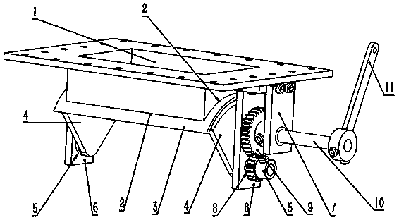
Figure 1
Abstract
Description
technical field
[0001] The invention relates to an accessory for an LED lamp tube glass granular raw material bin, in particular to a switch valve for an LED lamp tube glass granular raw material storage bin. Background technique
[0002] The raw material for the production of LED lamp glass is granular material. The switch valve of the traditional LED lamp tube glass granular raw material warehouse adopts a plug-in switch method. When this traditional switch valve is in use, on the one hand, it often jams. Failure, on the other hand, is likely to lead to lax sealing and frequent leakage of raw materials. Contents of the invention
[0003] The purpose of the present invention is to solve the above-mentioned existing problems, and provide a switch valve for an LED lamp tube glass granular raw material storage bin, which can be easily and conveniently opened or closed, with small resistance, and is beneficial to avoid jamming.
[0004] The invention includes driven gears an...
Examples
Embodiment Construction
[0009] figure 1 As shown: the arc-shaped opening 2 under the rectangular valve body 1 is equipped with a closed valve 3 corresponding to the opening 2, and the support plates 4 on both sides of the closed valve 3 are movably installed on both sides of the valve body 1 through the rotating shaft 5 Below the support seat A6, a support seat B7 is provided at intervals outside the support seat A6 on one side of the valve body. The driven gear 8 mounted on the rotating shaft 5 is in transmission engagement with the drive gear 9 at the inner end of the drive shaft 10 between the two. A handle 11 is provided at the outer end of the shaft 10 passing through the support seat B7.
[0010] In this technical solution: when the handle 11 is installed and used, it can be switched manually, or connected with a pneumatic device to realize the switch through pneumatic rotation.