
An acid mine wastewater treatment device for energy saving and emission reduction
A technology of acid mine wastewater and treatment device, which is applied in mining wastewater treatment, water/sewage treatment, water treatment parameter control, etc. Time, mix simple effects
Patent Information
- Authority / Receiving Office
- CN · China
- Patent Type
- Patents(China)
- Current Assignee / Owner
- Publication Date
- 2021-02-19
Smart Images
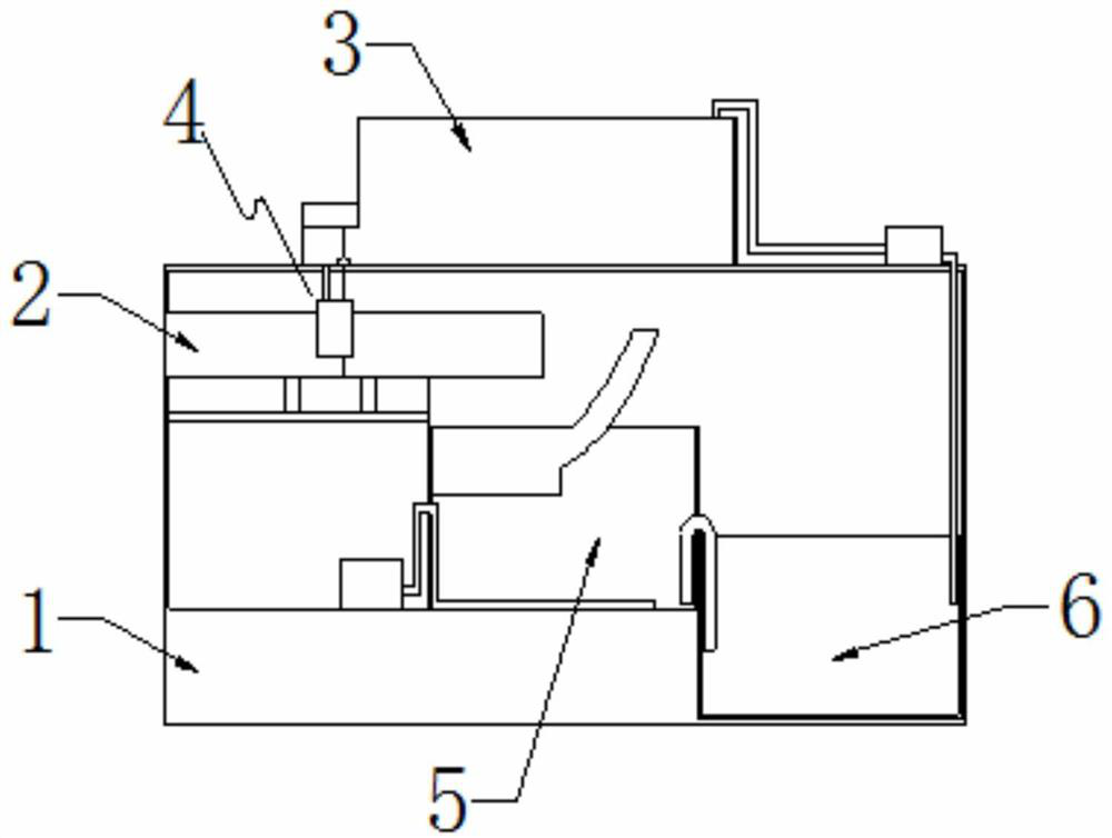
Figure 1 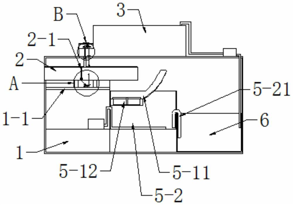
Figure 2 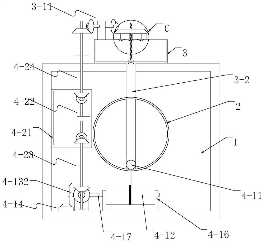
Figure 3
Abstract
Description
technical field
[0001] The invention relates to the technical field of mine wastewater treatment, in particular to an acid mine wastewater treatment device for energy saving and emission reduction. Background technique
[0002] During the mining of coal mines or various non-ferrous metal mines and the stacking of waste ores, the pyrite associated with the ore bed is often exposed to the air and groundwater or surface water. Through a series of chemical and biological oxidation processes, the near-neutral groundwater is transformed It is acidic mine wastewater with low pH, high Fe, SO42-, and coexistence of various heavy (like) metal ions (Cd, Pb, Cu, Zn, As, etc.). Acid mine wastewater has the characteristics of complex pollution components, large fluctuations in water volume, scattered discharge points, and difficulty in control. If such wastewater is discharged randomly without effective treatment, it will seriously pollute surface water and land resources, and threaten cr...
Examples
Embodiment
[0032] Example: such as Figure 1-11 As shown, an acid mine wastewater treatment device for energy saving and emission reduction, the acid mine wastewater treatment device includes a base 1, an energy saving mechanism 4, and a mixing pool 5, and the base 1 is sequentially installed with a storage tank 3 and a water inlet pipe from top to bottom 2. Energy-saving mechanism 4, mixing tank 5, sedimentation tank 6, water inlet pipe 2, energy-saving mechanism 4, mixing tank 5, sedimentation tank 6 are installed in the base 1 from left to right, and the storage box 3 is fixed on the base by screws 1, the upper end surface, the water inlet pipe 2 is welded inside the base 1, the energy-saving mechanism 4 is fixed on the base 1 by screws, the mixing tank 5 and the sedimentation tank 6 are welded on the base 1, and the mixing tank 5 and the sedimentation tank 6 are stepped The energy-saving mechanism 4 obtains power from the water inlet pipe 2, the energy-saving mechanism 4 controls the...