

Concrete grouting equipment and grouting method
A technology of concrete and equipment is applied in the field of concrete grouting equipment and grouting to achieve the effect of improving conveying efficiency
Patent Information
- Authority / Receiving Office
- CN · China
- Current Assignee / Owner
- Publication Date
- 2021-07-13
Smart Images

Figure 1 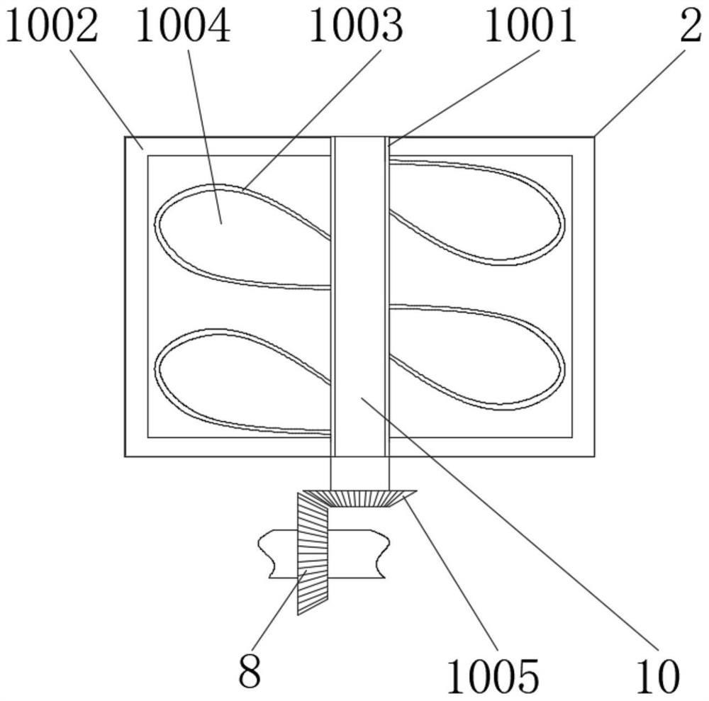
Figure 2 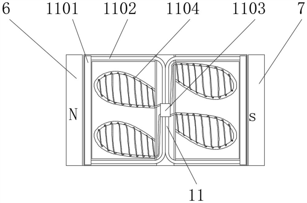
Figure 3
Abstract
Description
technical field
[0001] The invention relates to the technical field of building construction, in particular to a concrete grouting equipment and a grouting method. Background technique
[0002] Concrete grouting equipment is a professional construction tool used for chemical grouting and structural reinforcement of cracks, expansion joints, construction joints and structural joints in various buildings and underground concrete wood works. Generally, the grouting material is injected into the barrel Store, and then use the high-pressure pump to transport the grout to the required construction site.
[0003] There are still some defects in the existing concrete grouting equipment: First, the temperature at which the grouting material is transported to the construction site must be higher than 5°C. When the temperature in winter is lower than 5°C, manual stirring with hot water is required to ensure that the grouting material reaches the temperature of the construction site. I...
Examples
Embodiment Construction
[0023] The following will clearly and completely describe the technical solutions in the embodiments of the present invention with reference to the accompanying drawings in the embodiments of the present invention. Obviously, the described embodiments are only some, not all, embodiments of the present invention. Based on the embodiments of the present invention, all other embodiments obtained by persons of ordinary skill in the art without making creative efforts belong to the protection scope of the present invention.
[0024] see Figure 1-3 , a concrete grouting equipment, comprising a hopper 1, the bottom of the hopper 1 is fixedly connected with a material cylinder 2, a motor 3 is fixedly installed on one side of the bottom of the material cylinder 2, the rotating shaft of the motor 3 is fixedly connected with a drive shaft 4, and one end of the drive shaft 4 The top is fixedly connected with the screw pump 5, the bottom of the barrel 2 is provided with a round hole 502, ...