
Pebble bed pipe jacking structure and pebble bed pipe jacking construction method
A pebble layer and pipe jacking technology, which is used in earth-moving drilling, wellbore lining, tunnel lining and other directions, can solve the problems of small effect of construction technology, and achieve the effect of reducing ground subsidence and avoiding slurry running.
Patent Information
- Authority / Receiving Office
- CN · China
- Current Assignee / Owner
- Publication Date
- 2022-03-01
Smart Images
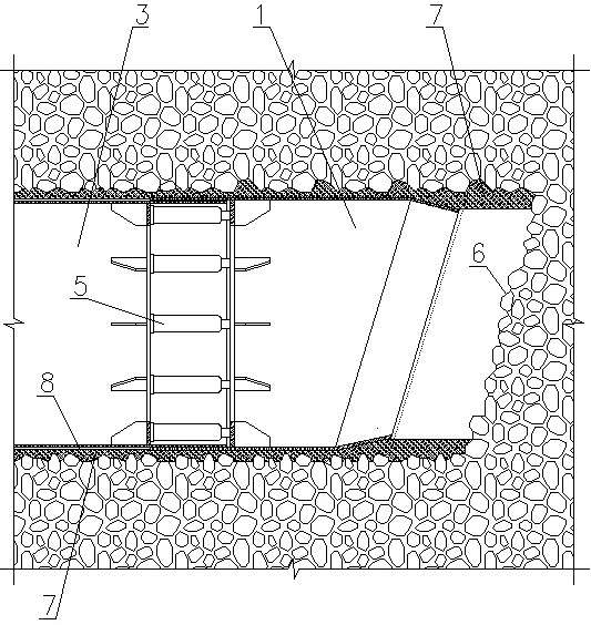
Figure 1 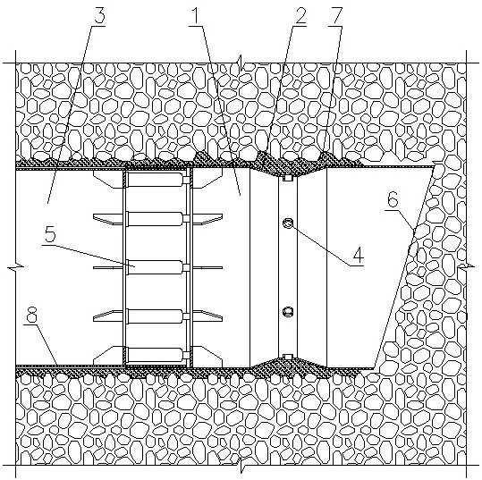
Figure 2 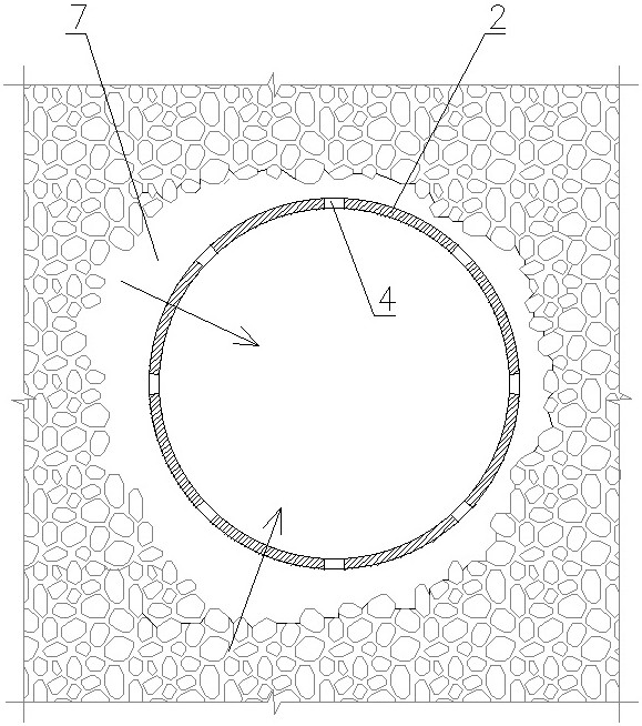
Figure 3
Abstract
Description
technical field
[0001] The invention belongs to the technical field of civil engineering construction, and in particular relates to a pipe jacking structure and a pipe jacking construction method. Background technique
[0002] When the pipeline is laid under the road, the pipe jacking method is often used to reduce the impact on the road traffic. If the soil layer that the pipe jacking passes is a pebble layer with large particle size and low clay content, the road surface will often have a large settlement after pipe jacking construction. This is mainly because all pebbles that affect the pipe jacking must be removed during pipe jacking. Even if a certain pebble affects only a small part of the pipe, it must be removed in its entirety. Finally, large pits and voids will be left around the tube. Such pits and voids make the upper soil of the pipeline lose its support, gradually collapse, and finally cause the road surface to subside. In addition, the pebbles at the bottom...
Examples
Embodiment 1
[0050] In the pipe jacking construction of general linear construction, a tool head 1 and a pipe 3 are included. The front end of the tool head 1 is directly sleeved on the pipe 3, and the pipe 3 is provided with a grouting hole. Drag-reducing mud 8 is injected into the soil. The existence of drag-reducing mud 8 reduces the friction between the outer wall of pipeline 3 and the soil, reduces the resistance of pipe jacking, and protects the outer wall of pipeline 3 at the same time.
Embodiment 2
[0052] In this embodiment, the pipe jacking construction includes a tool head 1 and a pipeline 3. In this embodiment, the tool head 1 has a deviation correction function. The tool head 1 is connected to the pipeline 3 through several jacks 5, and the elongation of the jacks 5 is controlled. Different, to control the deflection of the tool head 1 in the pipe jacking axial direction, and further control the direction of pipe jacking.
[0053] The pipe 3 is provided with a grouting hole through which the drag-reducing mud 8 is injected between the outer wall of the pipe 3 and the soil. The existence of the drag-reducing mud 8 reduces the friction between the outer wall of the pipe 3 and the soil, and reduces pipe resistance while protecting the outer wall of the pipe 3.
[0054] Such as figure 1 As shown, the present invention discloses a pebble layer pipe jacking structure. The tool head 1 is provided with an extruding section that is radially inward toward the center of the to...
Embodiment 3
[0056] Such as figure 2 As shown, in this embodiment, the extrusion section is the extrusion ring 2 arranged in the middle of the tool head 1, the extrusion ring 2 is sunken toward the center of the tool head 1, and several extrusion holes are provided on the extrusion ring 2 4. In order to ensure the extrusion efficiency of the filling material 7, the extrusion hole 4 is preferably set at the smallest diameter of the extrusion ring 2, that is, the lowest part of the outer surface of the tool head 1. Such a structure prevents the filling material 7 from accumulating on the tool head 1 . The filling material 7 enters the depression outside the extrusion ring 2 through the extrusion hole 4, and when the tool head 1 is pushed in, the filling material 7 is squeezed into the gap between the tool head 1, the pipe 3 and the pebble soil.
[0057] The cross-sectional shape of the extrusion ring 2 can be: isosceles trapezoid, right-angled trapezoid, triangle, bell mouth shape.
[005...