
Light-emitting device and illuminating device
A technology for light-emitting devices and light-emitting elements, which is applied to electrical components, electric solid-state devices, circuits, etc., can solve the problems of not being able to improve the luminous efficiency of phosphors, and the luminous efficiency of light-emitting devices, so as to reduce uneven hues and suppress luminescence. Efficiency drop and joint strength enhancement effect
Patent Information
- Authority / Receiving Office
- CN · China
- Patent Type
- Applications(China)
- Current Assignee / Owner
- Publication Date
- 2007-03-21
- Estimated Expiration
- Not applicable · inactive patent
Smart Images
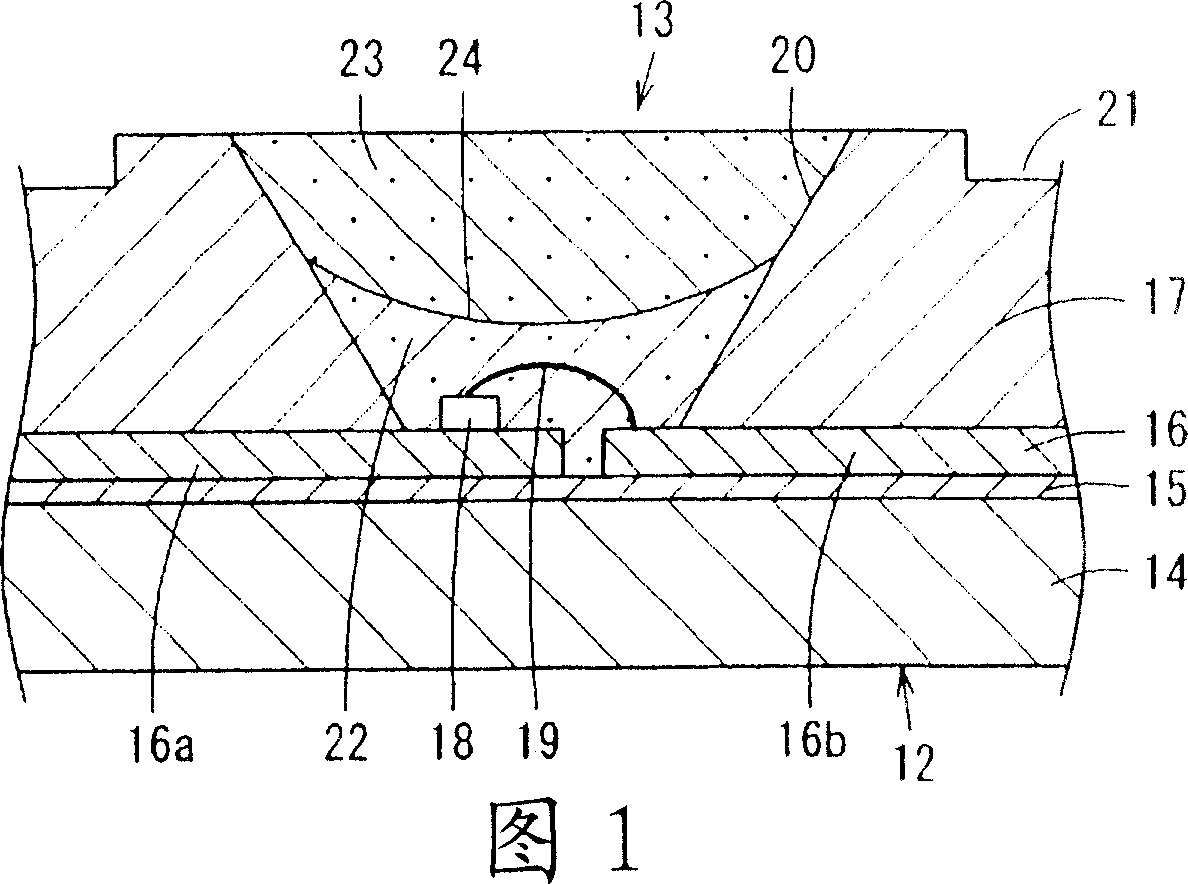
Figure 1 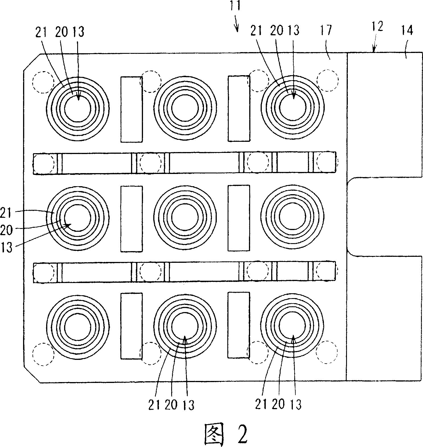
Figure 2 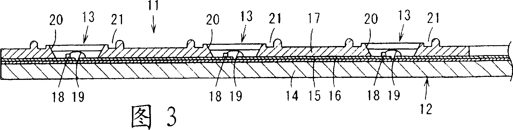
Figure 3
Abstract
Description
technical field
[0001] The present invention relates to a light-emitting device using a light-emitting element as a light source, and an illuminating device with the light-emitting device. Background technique
[0002] Conventionally, in a light-emitting device using a light-emitting diode element, which is a solid-state light-emitting element, as a light source, there is known a surface mount type light-emitting device in which a light-emitting diode element is disposed on a substrate and a resin is filled to cover the light-emitting diode element. device.
[0003] And, in order to utilize this light-emitting device to emit white light, the following technology is known: said device mixes the blue light emitted by the blue light-emitting diode element and the yellow light emitted by the yellow light-emitting diode element (for example, refer to the patent document 1).
[0004] In addition, a technique is known in which a blue light-emitting diode element is covered with a...
Examples
Embodiment Construction
[0063] Hereinafter, embodiments of the present invention will be described with reference to the drawings.
[0064] 1 to 4 show a first embodiment of the present invention. 1 is a partial enlarged cross-sectional view of a light emitting device, FIG. 2 is a top view of the light emitting device, FIG. 3 is a cross-sectional view of the light emitting device, and FIG. 4 is a table showing the relationship between the amount of scattering agent added and the light beam of the light emitting device.
[0065] As shown in FIGS. 2 and 3 , the light-emitting device 11 has a base material 12 on which a plurality of light-emitting element arrangement portions 13 are formed, for example, in a matrix of three rows and three columns.
[0066] The base material 12 has: a plate-shaped substrate 14 of aluminum (Al) or nickel (Ni), glass epoxy resin, etc. with heat dissipation and rigidity; an insulating layer 15 formed on the substrate 14; lead frame 16 ; and reflector 17 ′ formed on substra...