
Light emitting device, surface light source, liquid crystal display device, and lens
a liquid crystal display and light-emitting technology, which is applied in the direction of semiconductor devices for light sources, lighting and heating apparatus, instruments, etc., can solve the problems of emitting devices, color unevenness becomes prominent, and cost increases, and achieve the effect of reducing the total reflection componen
Patent Information
- Authority / Receiving Office
- US · United States
- Patent Type
- Applications(United States)
- Current Assignee / Owner
- Publication Date
- 2013-05-09
- Estimated Expiration
- Not applicable · inactive patent
Smart Images
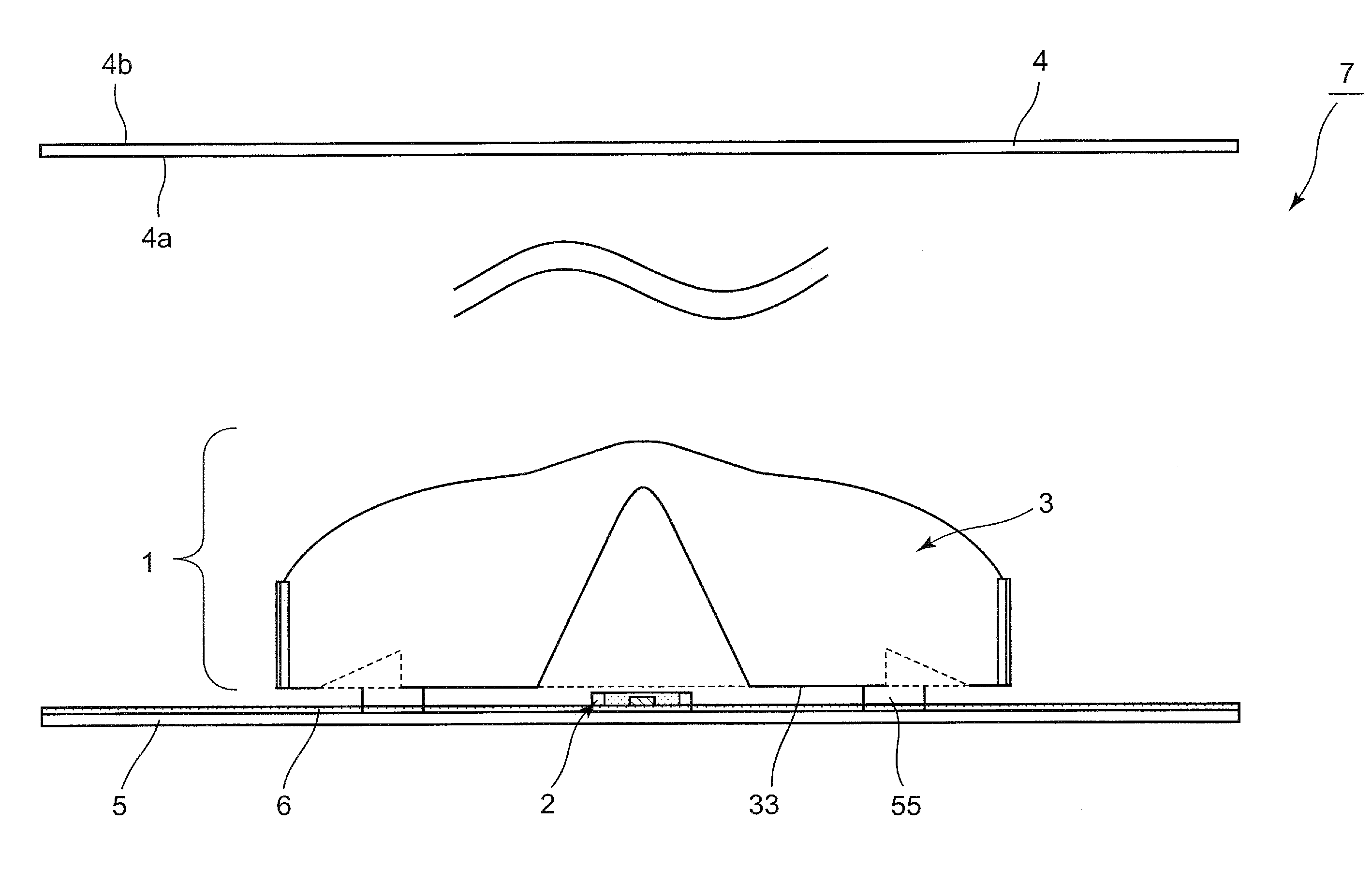
Figure 1 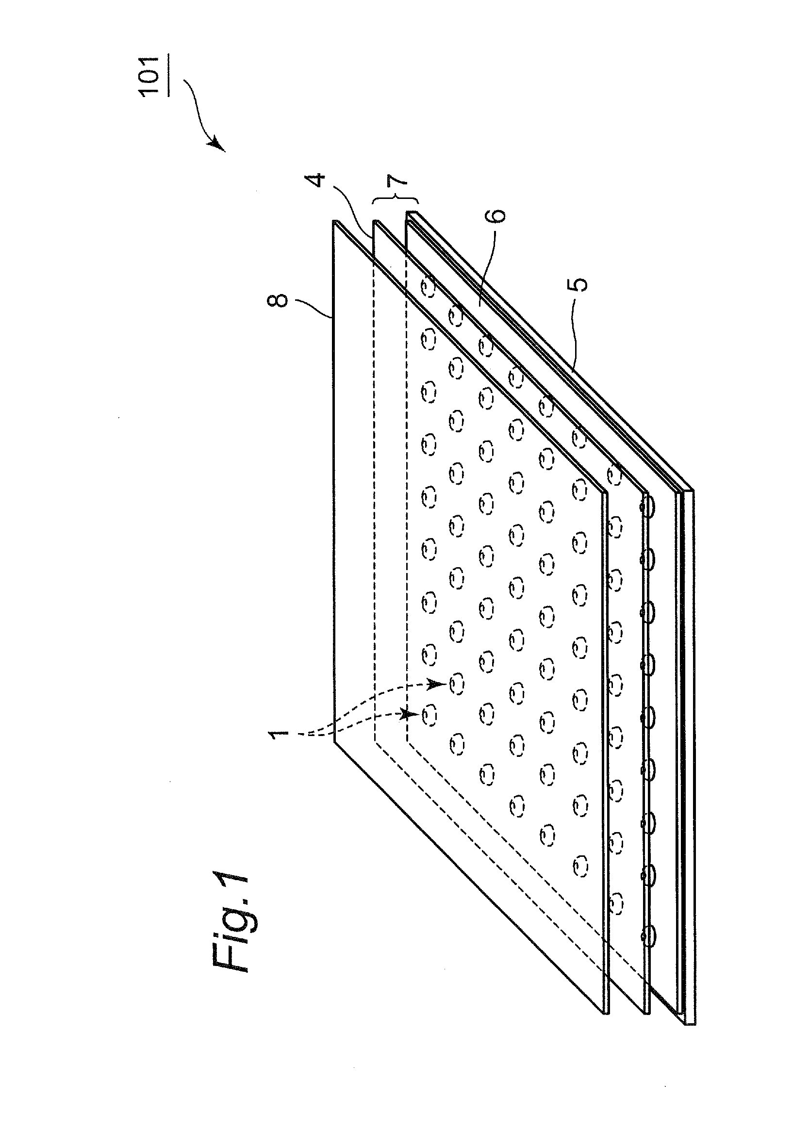
Figure 2 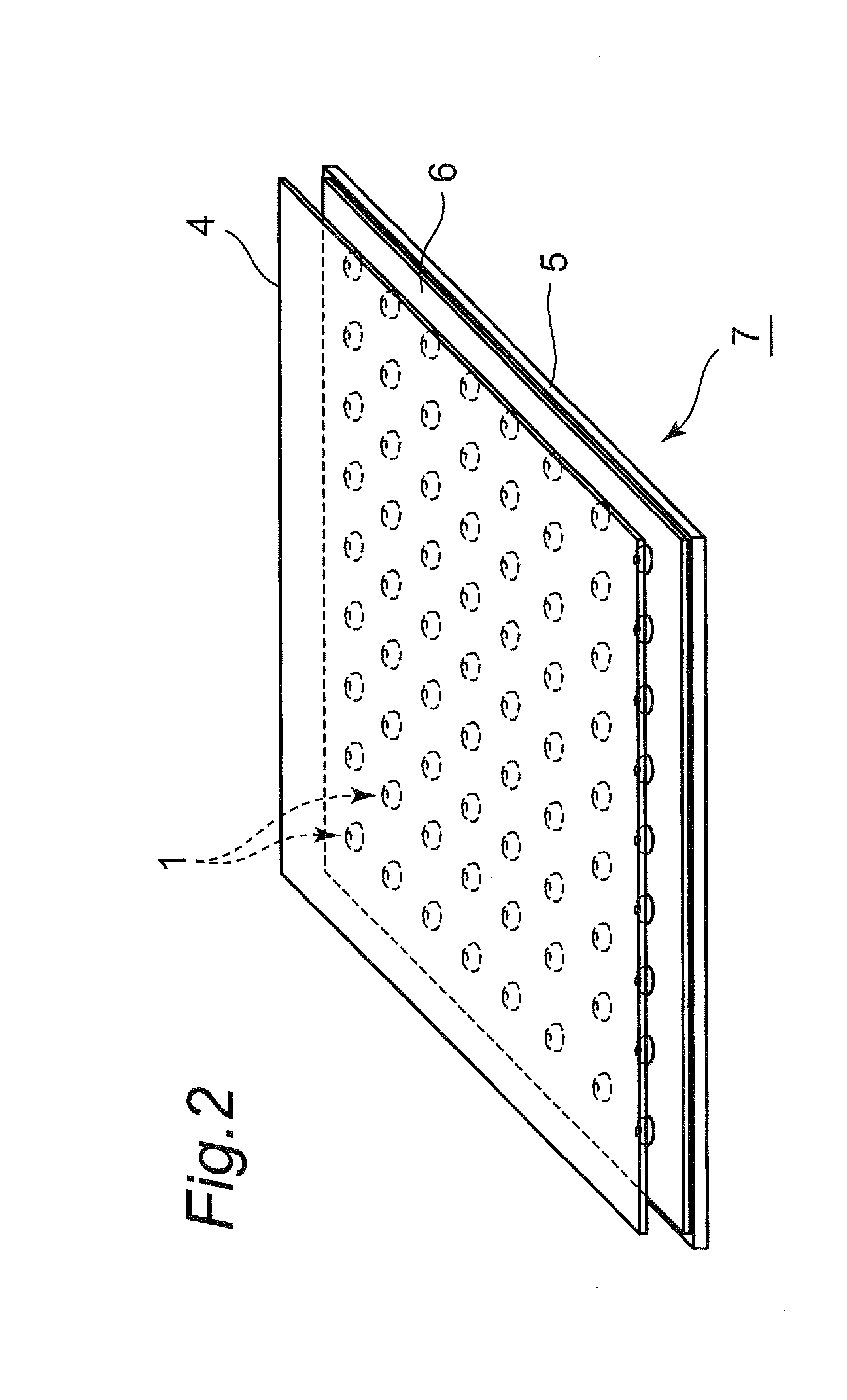
Figure 3
Abstract
Description
CROSS-REFERENCE TO RELATED APPLICATIONS
[0001] This is a continuation application of International Application No. PCT / JP2012 / 001369, with an international filing date of Feb. 29, 2012, which claims priority of Japanese Patent Application No.: 2011-121373 filed on May 31, 2011, the content of which is incorporated herein by reference.BACKGROUND OF THE INVENTION
[0002] 1. Technical Field
[0003] The present disclosure relates to a light emitting device which expands directionality of light from a light source such as a light emitting diode (hereinafter simply referred to as an “LED”) by a lens. The disclosure also relates to a surface light source including a plurality of the light emitting devices, a liquid crystal display device in which the surface light source is disposed as a backlight at the back of a liquid crystal display panel, and a lens included in the light emitting device.
[0004] 2. Description of the Related Art
[0005] In a backlight of a conventional large-size liquid crystal dis...
Examples
first embodiment
[0041]FIG. 1 is a view illustrating a whole schematic configuration of a liquid crystal display device 101 according to a first embodiment of the disclosure. The liquid crystal display device 101 includes a liquid crystal display panel 8 and a surface light source 7 that is disposed on the back side (an opposite side to a display surface) of the liquid crystal display panel 8. The surface light source 7 includes a light emitting device 1 and a diffuser plate 4 that is disposed opposite to the light emitting device 1. The surface light source 7 is described in detail later in a second embodiment.
[0042]A plurality of the light emitting devices 1 are disposed opposite to the diffuser plate 4 while dispersed in a planar manner, and the light emitting devices 1 irradiate a rear surface (irradiated surface) of the diffuser plate 4 opposite to the light emitting device 1 with the light having the equalized illuminance. The light is diffused by the diffuser plate 4 to output from a surface ...
second embodiment
[0044]The surface light source 7 according to a second embodiment of the disclosure will be described in detail. FIG. 2 is a configuration diagram of the surface light source 7. As described above, the surface light source 7 includes the plurality of light emitting devices 1 and the diffuser plate 4 that is disposed so as to cover the light emitting devices 1. Each of the light emitting devices 1 includes a light source 2 and a lens 3 that is disposed while covering the light source 2. The diffuser plate 4 extends in a direction orthogonal to the optical axis of the light source 2. The light emitting devices 1 are disposed in a bottom portion in a chassis, and an opening of the chassis that is provided opposite to the bottom portion is closed by the diffuser plate 4 to form the surface light source 7. The light emitting devices 1 may be disposed in any manner as long as they are disposed opposite to the whole surface or the substantially whole surface of the diffuser plate 4 while d...
third embodiment
[0049]The light emitting device 1 according to a third embodiment of the disclosure will be described in detail. FIGS. 4, 5A, and 5B are views illustrating a configuration of the light emitting device 1. As described above, the light emitting device 1 includes the light source 2 and the lens 3 that radially expands the light emitted from the light source 2. For example, the light emitting device 1 radiates light onto the irradiated surface 4a of the diffuser plate 4 at an optical axis A and at the substantially circular shape around the optical axis A. That is, directionality of the light emitted from the light source 2 is expanded by the lens 3, whereby the wide range of the irradiated surface 4a of the diffuser plate 4 is illuminated at the optical axis A and about the optical axis A. The illuminance distribution of the irradiated surface 4a becomes the maximum at the optical axis A, and monotonously decreased toward a surrounding region from the optical axis A.
[0050]An LED is use...