

Methods and apparatus for reducing signal degradation
a signal degradation and signal technology, applied in the field of methods and apparatus for reducing signal degradation, can solve the problems of divergence, inability to work well with conventional coupling cancellation units, and inability to meet the requirements of a repeater transmission environment, and achieve the effect of minimizing the estimated error
Patent Information
- Authority / Receiving Office
- US · United States
- Patent Type
- Applications(United States)
- Current Assignee / Owner
- Publication Date
- 2002-04-04
Smart Images
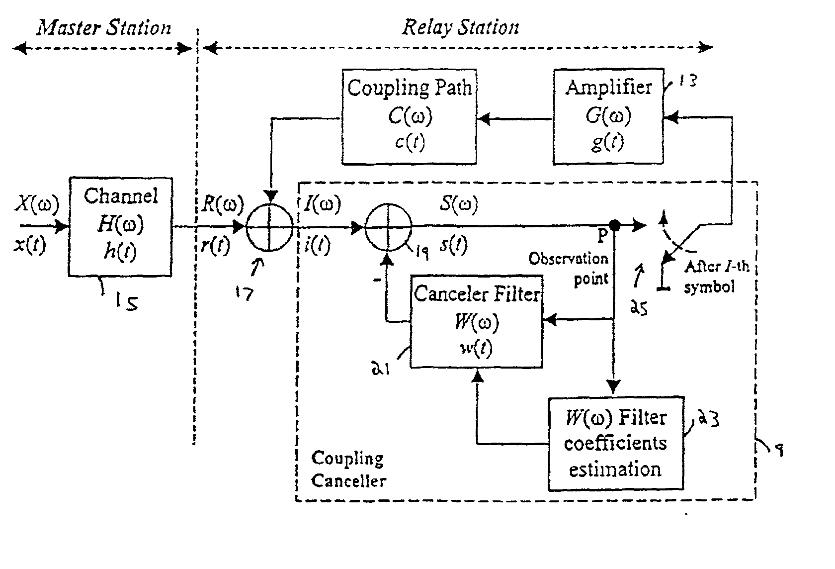
Figure 1 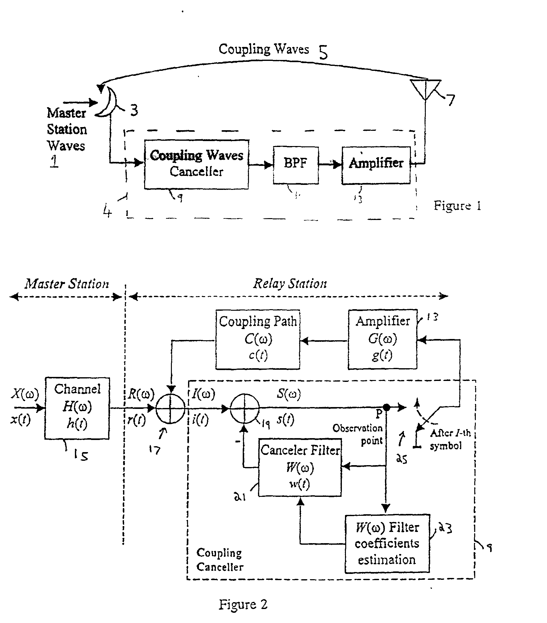
Figure 2 
Figure 3
Abstract
Description
[0001] The present invention relates to methods and devices for reducing noise in a signal received and re-transmitted by a relay station. The invention is particularly suitable if the signal received by the relay station includes multipath interference. The invention further relates to a relay station, such as a single frequency relay station.
[0002] The ISDB-T (Integrated Services Digital Broadcasting--Terrestrial) BST-OFDM (band segmented transmission--orthogonal frequency division multiplexing) system is an example of what is often called a "single frequency network" (SFN).
[0003] In fact, the signal is generally made up of multiple carrier signals. Each carrier has a finite, though narrow, frequency range, and when we talk about the frequency of a single carrier signal, we mean the center frequency of the narrow range. For multi-carrier transmission, such as OFDM in an ISDB-T system, each carrier has a different respective center frequency, and the frequencies are orthogonal to e...
Examples
Embodiment Construction
[0052] Like the conventional system discussed above, the present embodiment has the general structure illustrated in FIG. 1, but the coupling waves cancellation unit 9 is as illustrated in FIG. 2. The optional BPF 11 of FIG. 1 is omitted from FIG. 2 for simplicity. Likewise, FIG. 2 omits any A / D converter(s) in the system.
[0053] FIG. 2 shows the detail of the coupling wave cancellation unit and the principle of canceling coupling waves between the transmitting and receiving antennas of the broadcasting wave relay station. The master signal is x(t) (in the frequency domain X(.omega.)), which is subject to multipath interference h(t) (H(.omega.), in the frequency domain, is the multipath channel transfer function), in the channel 15 between the master station and the relay station, to produce a signal r(t) (R(.omega.) in the frequency domain).
[0054] The signal R((.omega.) from the master station is given by
R(.omega.)=X(.omega.).multidot.H(.omega.) (1)
[0055] A coupling wave is added to...