

PWM rectifier having de-coupled power factor and output current control loops
Patent Information
- Authority / Receiving Office
- US · United States
- Current Assignee / Owner
- Publication Date
- 2002-04-02
- Estimated Expiration
- Not applicable · inactive patent
Smart Images
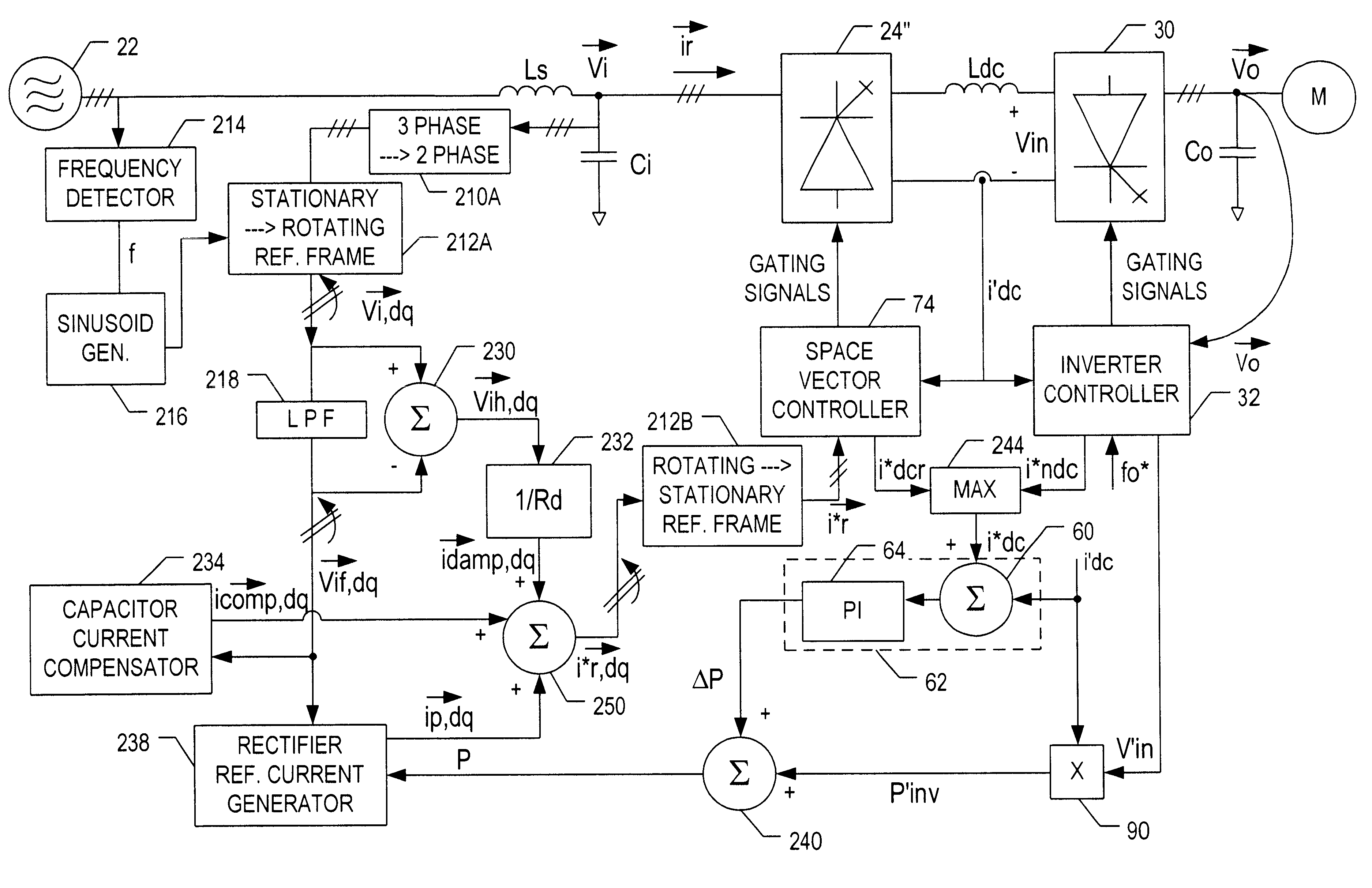
Figure 1 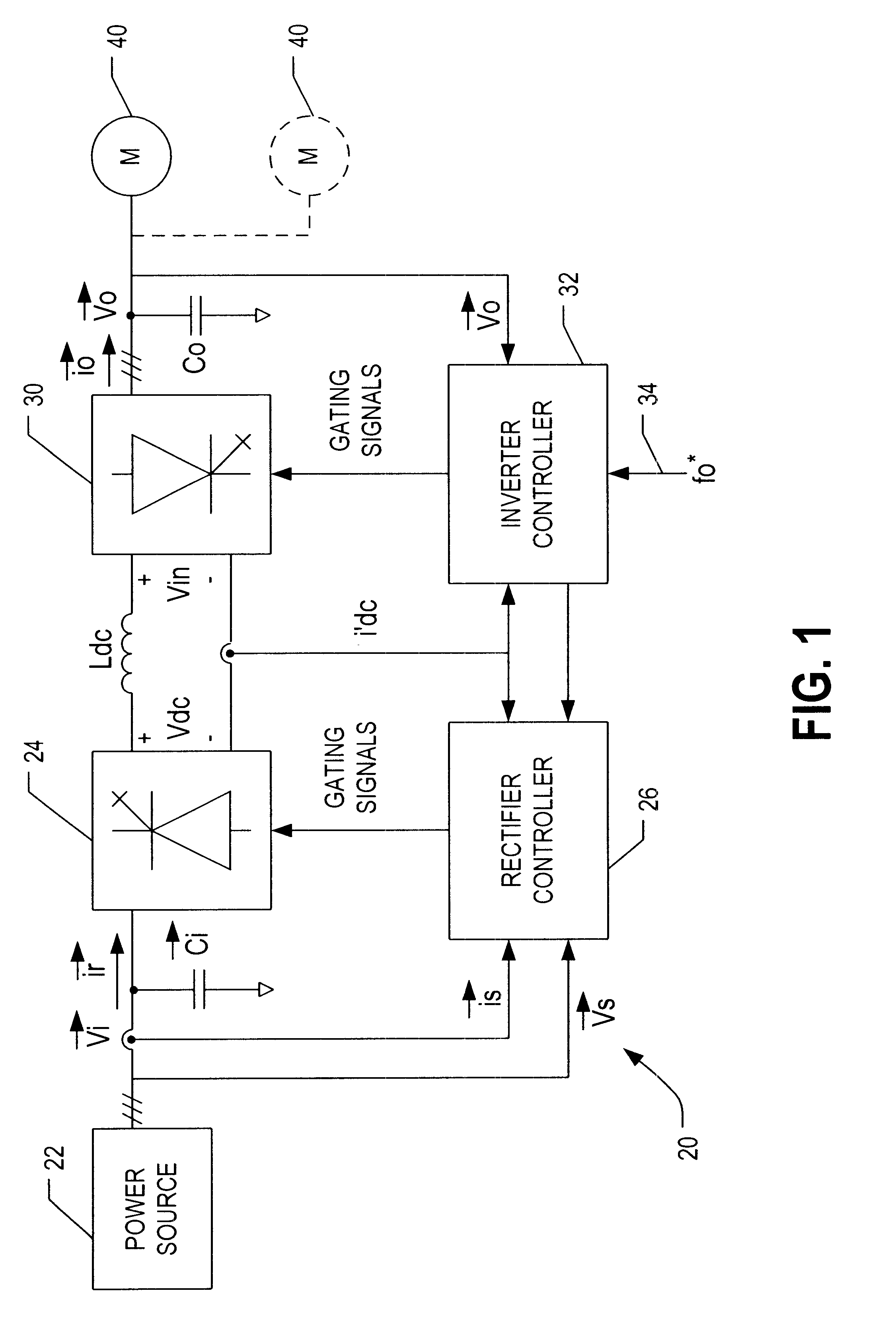
Figure 2 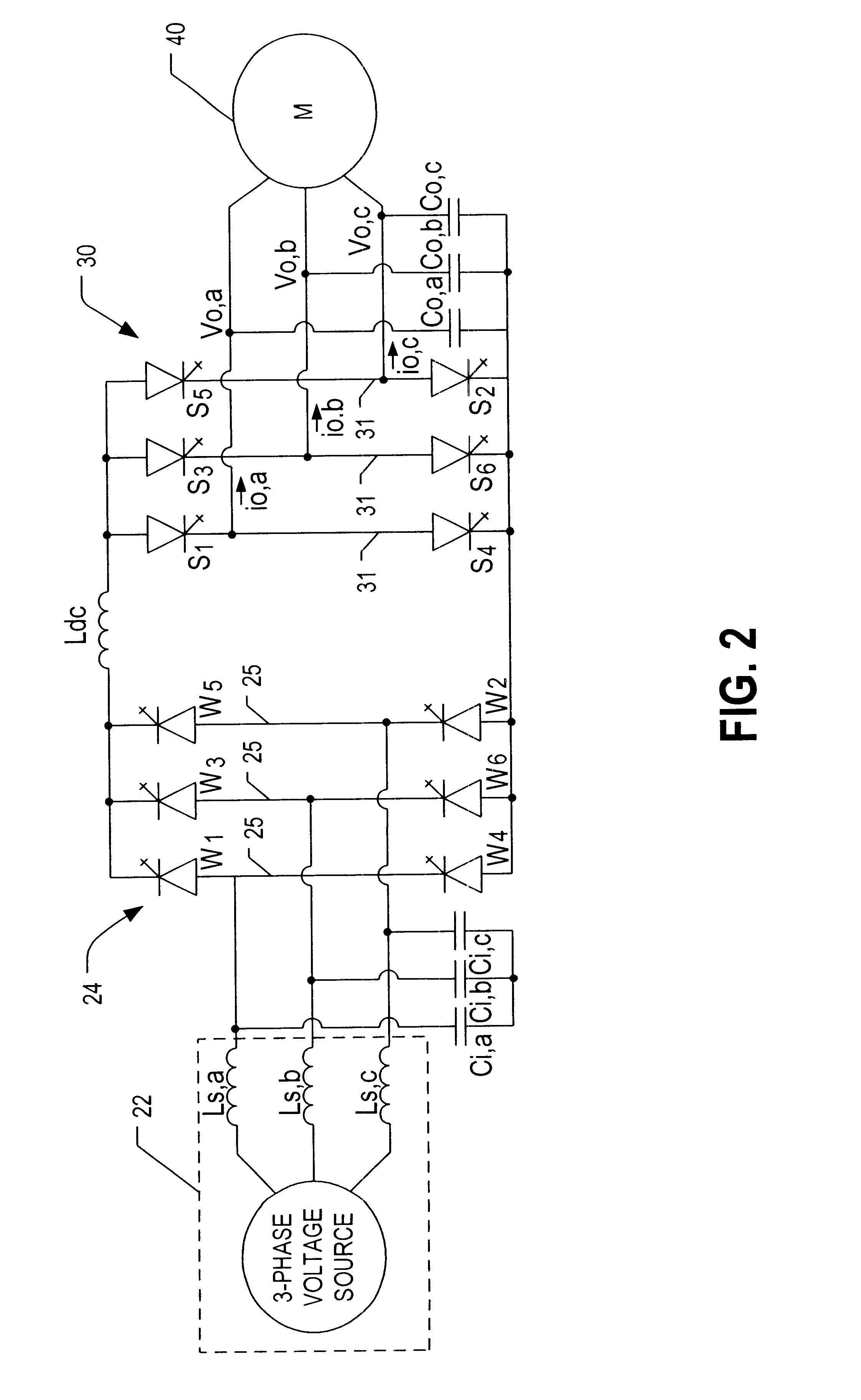
Figure 3
Abstract
Description
The invention generally relates to the field of power electronics. More particularly, the invention relates to a pulse-width modulated (PWM) rectifier wherein the reactive and active powers are controlled independent of one another for improved performance. The PWM rectifier has particular utility in a current source inverter (CSI) based drive for controlling one or more high power alternating current (a.c.) induction motors.BACKGROUND OF INVENTIONCSI-based a.c. motor drives are increasingly used in high power (e.g., 1,000.about.10,000 hp) applications. See, for instance, P. M. Espelage and J. M. Nowak, "Symmetrical GTO Current Source Inverter for Wide Speed Range Control of 2300 to 4160 volt, 350 to 7000hp, Induction Motors", IEEE IAS Annual Meeting, pp 302-307, 1988. Compared with voltage source inverter fed drives, the CSI drive features simple structure, reliable short circuit protection, four quadrant operation capability and nearly sinusoidal output voltage and current wavefor...
Examples
Embodiment Construction
The detailed description is divided into three parts. The first portion of the discussion relates to active damping control in order to suppress resonance modes. The second part of the discussion centres on the enhancement of CSI-based drives through the use of feedforward control. These portions of the description are also described in co-pending U.S. application Ser. Nos. 09 / 515,289 and 09 / 516,974 and are repeated herein for convenience. The third part of the detailed description focuses on a PWM rectifier having de-coupled power factor and output current control loops and on the use of such a rectifier in an improved CSI-based drive such as discussed in the first two portions of this description.
1. Active Damping Control
Referring to the drawings, FIG. 1 shows a schematic block diagram of a drive 20 for control of one or more a.c. induction motors 40. The drive 20 comprises a rectifier 24 coupled to a current source inverter 30 via a d.c. link choke or inductor L.sub.dc. The recti...