
Method of manufacturing nozzle plate and method of manufacturing liquid ejection head
Patent Information
- Authority / Receiving Office
- US · United States
- Current Assignee / Owner
- Publication Date
- 2008-09-11
- Estimated Expiration
- Not applicable · inactive patent
Smart Images
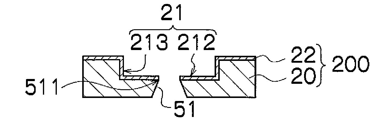
Figure 1 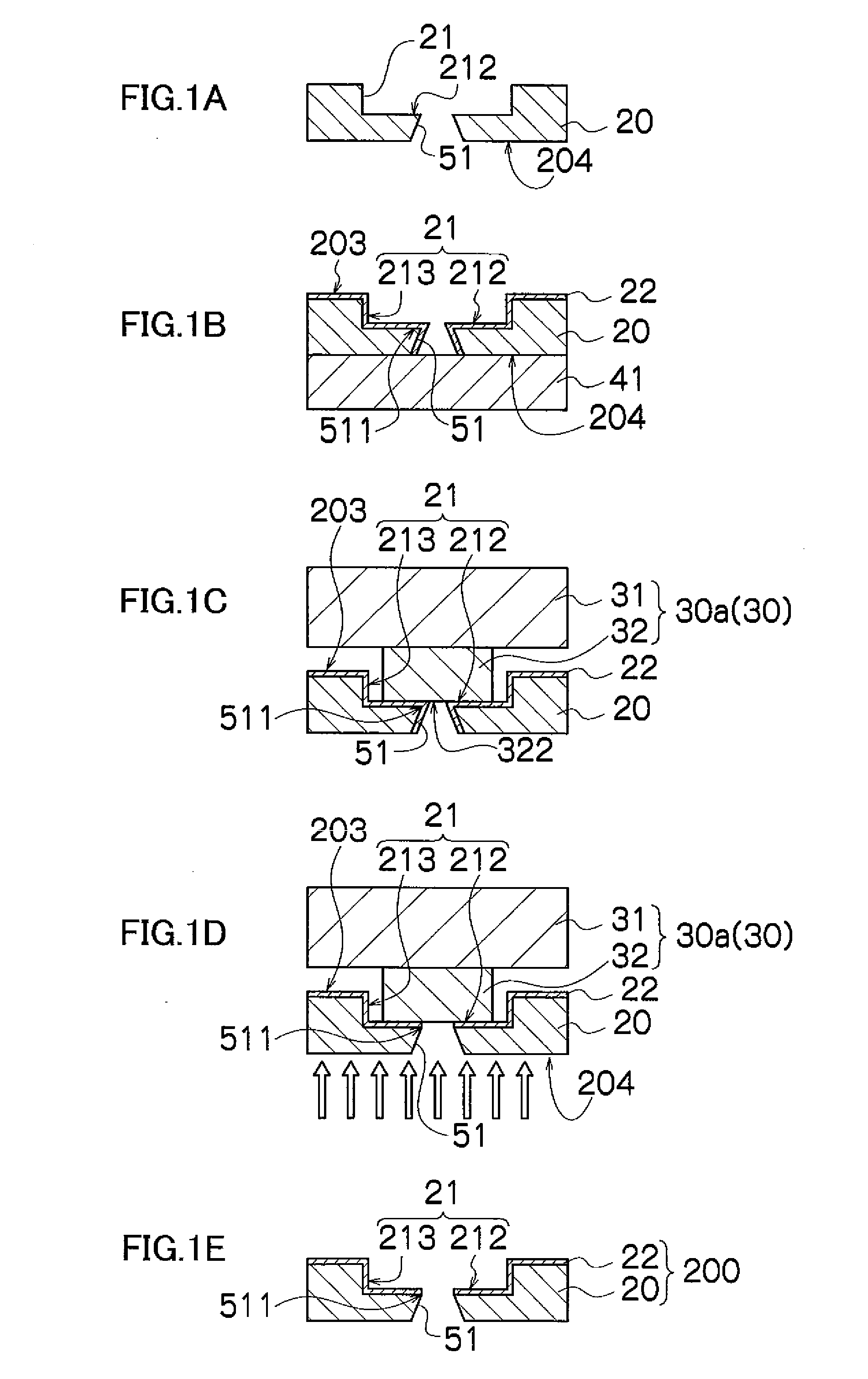
Figure 2 
Figure 3
Abstract
Description
BACKGROUND OF THE INVENTION
[0001] 1. Field of the Invention
[0002] The present invention relates to a method of manufacturing a nozzle plate and a method of manufacturing a liquid ejection head, by which a lyophobic (liquid-repellent) film is formed on a recess-shaped counterbore section.
[0003] 2. Description of the Related Art
[0004] There are methods for forming a lyophobic film on the liquid ejection surface of a nozzle plate formed with nozzles, in which the lyophobic film is not formed on the inner walls of the nozzles. For example, there are a method in which a lyophobic film is formed only on the liquid ejection surface of a nozzle plate after embedding a filling material into the nozzles, and a method in which a lyophobic film is formed over the whole surface of a nozzle plate, and the unwanted portions are then removed.
[0005] Japanese Patent Application Publication No. 9-267478 discloses a method where a lyophobic film is formed on the whole surface of a nozzle plate in which nozz...
Examples
first embodiment
[0047]To begin with, the method of manufacturing a nozzle plate relating to the invention will be described with reference to the step diagrams in FIGS. 1A to 1E.
[0048]Firstly, as shown in FIG. 1A, a recess-shaped counterbore section 21 and a nozzle 51 which opens in the bottom face 212 of the counterbore section 21 are formed in a flat substrate. By this means, an initial nozzle plate 20 having counterbore sections 21 and nozzles 51 is obtained.
[0049]Possible materials for the substrate of the nozzle plate 20 include a metal such as stainless steel (SUS), silicon (Si), and the like.
[0050]Possible methods for forming the counterbore sections 21 and the nozzles 51 include electroforming, dry etching, and wet etching.
[0051]The nozzles 51 according to the present embodiment have a tapered shape in which the diameter of the flow channel narrows continuously from the liquid supply surface 204 to the liquid ejection surface, which is the bottom surface 212 of the counterbore section 21, b...
second embodiment
[0070]Next, the method of manufacturing a nozzle plate will be described.
[0071]In the present embodiment, the plate used as the protective plate 30 shown in FIG. 1C and FIG. 1D is one where a film having resistance to the etching performed in the step of removing the lyophobic film 22 shown in FIG. 1D (hereinafter, called “etching-resistant film”) is formed at least on the top surface 322 of the projecting section 32.
[0072]The protective plate 30c shown in FIG. 3A has an etching-resistant film 34 formed only on the top surface 322 of the projecting section 32.
[0073]It is also possible to form an etching-resistant film 34 on the side walls 323 of the projecting section 32 and the flat surface 311 of the flat section 31, as well as on the top surface 322 of the projecting section 32, as shown in FIG. 3B illustrating the protective plate 30d.
[0074]A protective plate 30 (30c, 30d) formed with an etching-resistance film 34 of this kind is used in the process of manufacturing a nozzle p...
third embodiment
[0081]Next, the method of manufacturing a nozzle plate will be described.
[0082]In the present embodiment, the plate used for the protective plate 30 shown in FIGS. 1C and 1D is one having a lyophobic film formed on at least the top surface 322 of the protecting section 32.
[0083]The protective plate 30e shown in FIG. 4A has a lyophobic film 35 formed only on the top surface 322 of the projecting section 32.
[0084]It is also possible to form a lyophobic film 35 on the side walls 323 of the projecting section 32 and the flat surface 311 of the flat section 31, as well as on the top surface 322 of the projecting section 32, as in the protective plate 30d shown in FIG. 4B.
[0085]A protective plate 30 (30e, 30f) formed with a lyophobic film 35 of this kind is used in the process of manufacturing a nozzle plate shown in FIGS. 1A to 1E.
[0086]Furthermore, it is also possible to form the lyophobic film 35 on the whole surface of the protective plate 30 shown in FIGS. 1C and 1D.
[0087]If the top...