
Coil component, manufacturing method thereof, and circuit board on which coil component are mounted
Patent Information
- Authority / Receiving Office
- US · United States
- Current Assignee / Owner
- Publication Date
- 2017-04-20
Smart Images
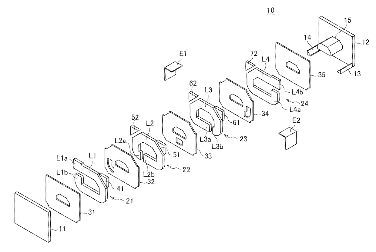
Figure 1 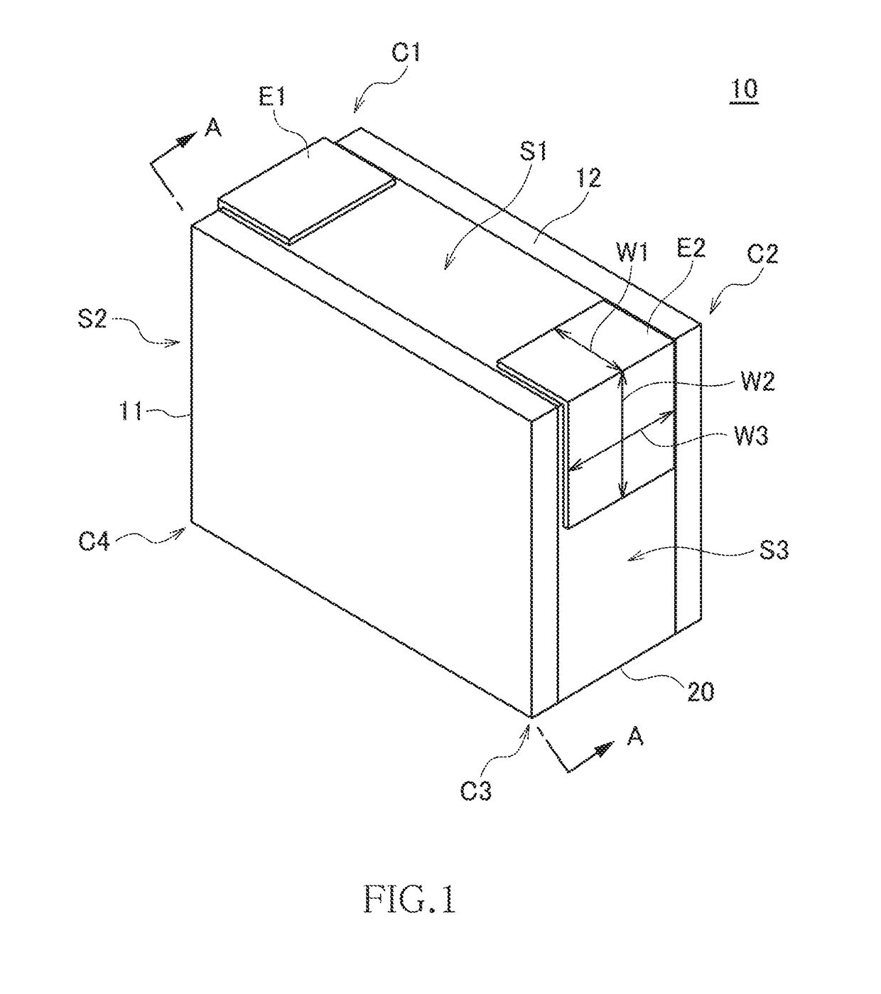
Figure 2 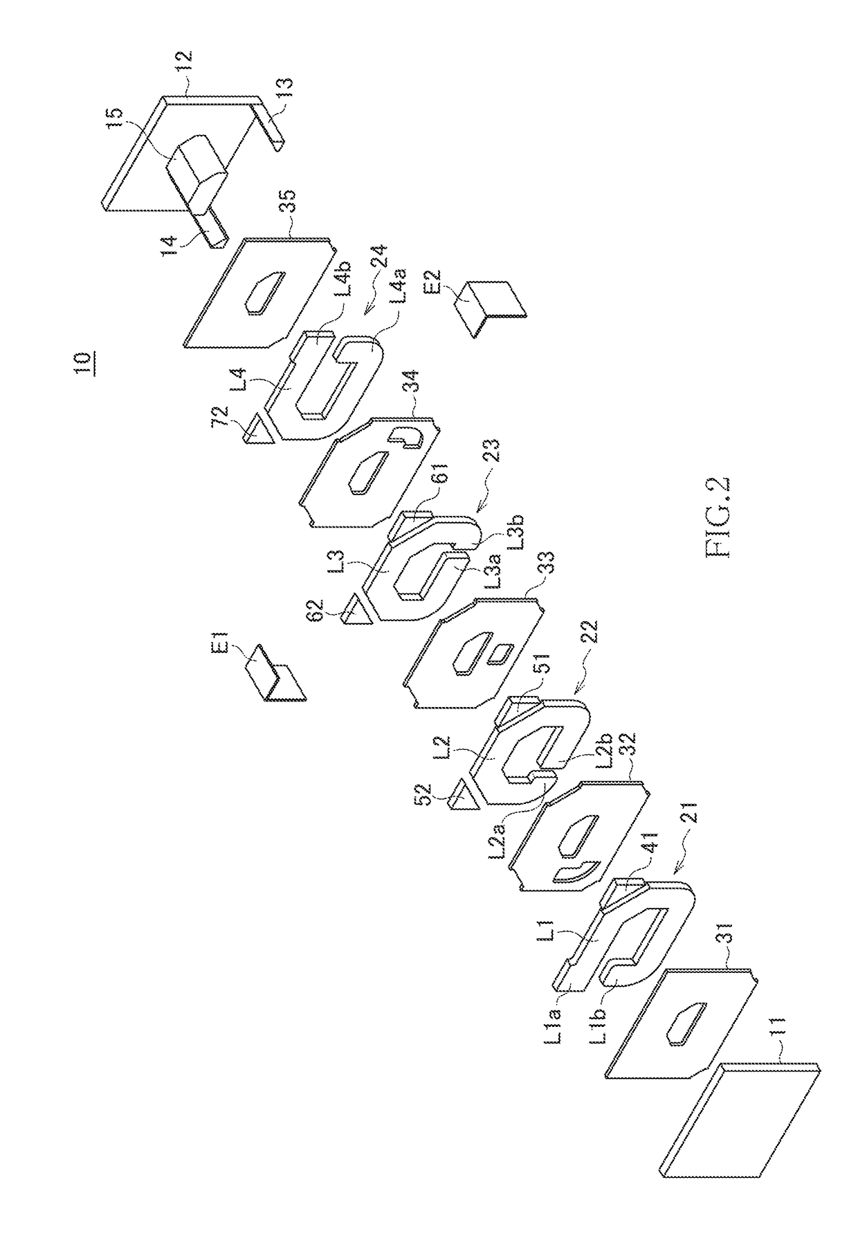
Figure 3
Abstract
Description
BACKGROUND OF THE INVENTION
[0001] Field of the Invention
[0002] The present invention relates to a coil component and a manufacturing method therefor and, more particularly, to a coil component suitably used for a power supply circuit and a manufacturing method therefor. The preset invention further relates to a circuit board on which such a coil component is mounted.
[0003] Description of Related Art
[0004] In a coil component used in a power supply circuit, a current higher than that in a coil component for signal transmission flows, so that the coil component used in a power supply circuit needs to have a lower DC resistance. To reduce a DC resistance, it is necessary to reduce a coil length and to increase the cross-sectional area of a coil conductor. On the other hand, to ensure a sufficient inductance, it is necessary to increase a coil length and to reduce a coil conductor width so as to form a larger loop. Thus, a trade-off relationship exists between the reduction in the DC resist...
Examples
Embodiment Construction
[0033]Preferred embodiments of the present invention will now be explained in detail with reference to the drawings.
[0034]FIG. 1 is a perspective view illustrating the outer appearance of a coil component 10 according to a preferred embodiment of the present invention. FIG. 2 is an exploded perspective view of the coil component 10. FIG. 3 is a cross-sectional view taken along the line A-A illustrated in FIG. 1.
[0035]The coil component 10 according to the present embodiment is a surface-mount type chip component that can be used as an inductor for a power supply circuit. As illustrated in FIGS. 1 to 3, the coil component 10 includes first and second magnetic members 11 and 12 and a coil layer 20 sandwiched between the first and second magnetic members 11 and 12.
[0036]The magnetic member 11 is a substrate made of a magnetic material such as a ferrite. As described later, in the manufacturing process of the coil component 10, the magnetic member 11 is used as a substrate, and the coil...