
Micro Generator System
a generator system and micro-generator technology, applied in the direction of generators/motors, machines/engines, nuclear engineering, etc., can solve the problems of inability to meet the existing demand for effectively powering microsystem applications, heavy conventional batteries, short-lived,
Patent Information
- Authority / Receiving Office
- US · United States
- Current Assignee / Owner
- Publication Date
- 2009-03-05
- Estimated Expiration
- Not applicable · inactive patent
Smart Images
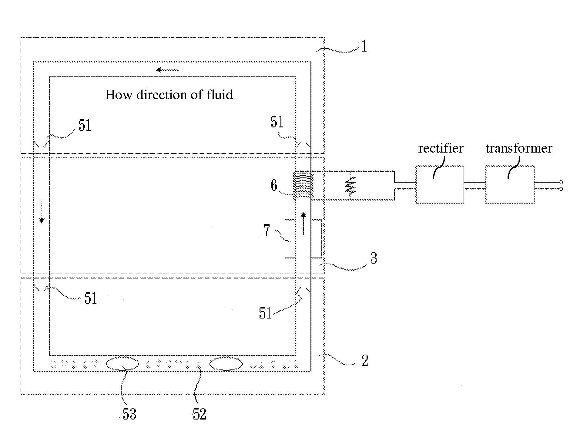
Figure 1 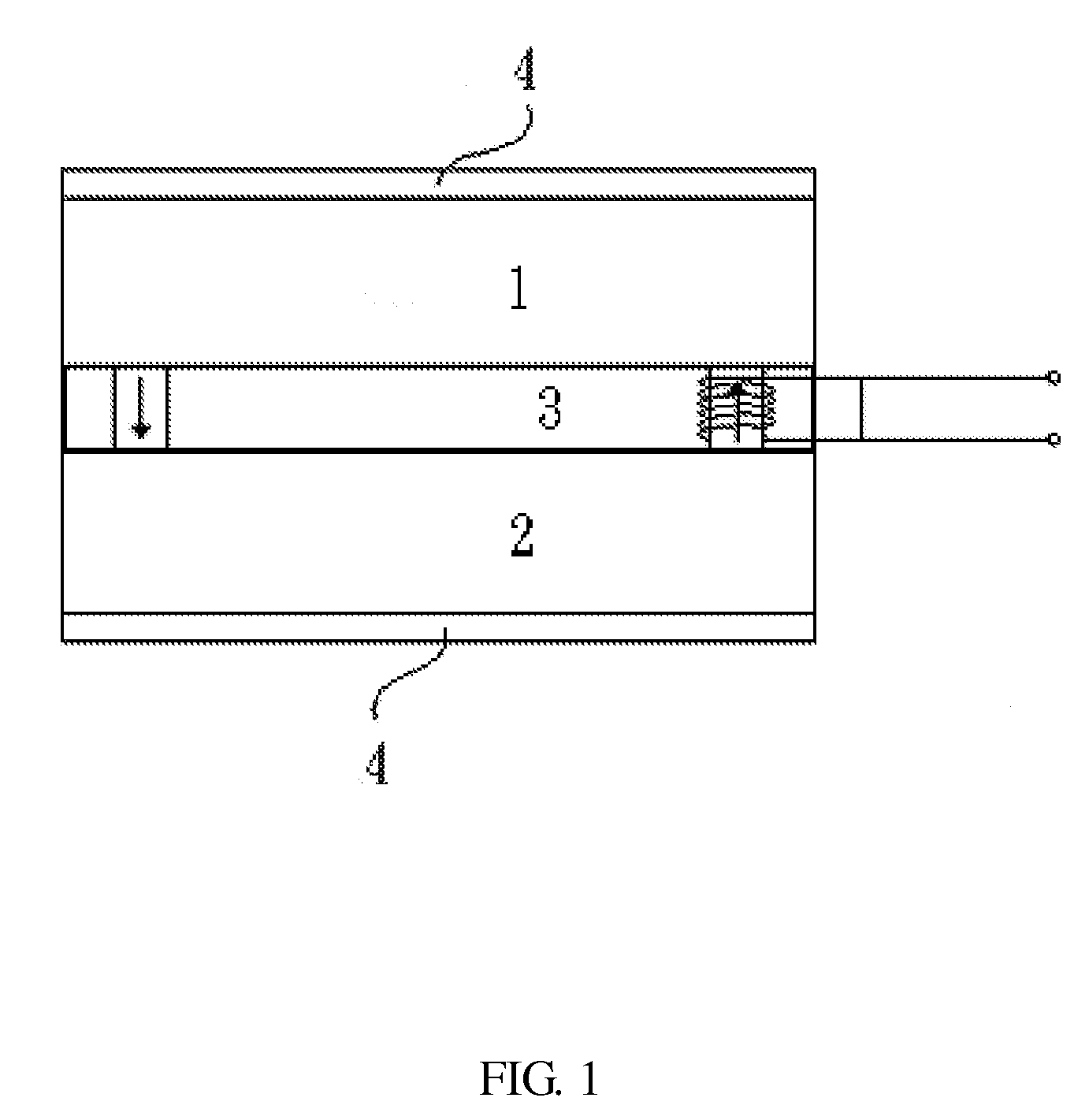
Figure 2 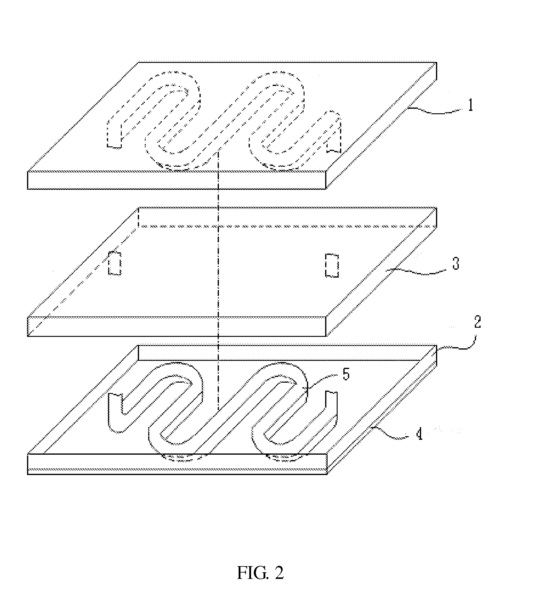
Figure 3
Abstract
Description
FIELD OF THE INVENTION
[0001] The micro generator system of the present invention can be used in low power devices such as vital sign monitoring device, pacemaker, and animal tracking device.DESCRIPTION OF PRIOR ART
[0002] In recent years, electronic devices and communications products are trending toward portable wireless features, giving rise to the production of high-performance components that are light, thin, short, and small, which in turn increases the need for micro power. Conventional batteries are heavy, short-lived, toxic and require recycling, all of which cannot meet the existing demand for effectively powering microsystem applications. For this reason, it is imperative to develop a new type of automatic and eco-friendly micro power generator.
[0003] A power supply system comprises four major components, i.e. energy source, energy access system, energy storage and drive mechanism. An ideal power supply system is one that can obtain energy sources from the surroundings, e.g. t...
Examples
example
[0011]FIG. 1 was a vertical schematic structural diagram and FIG. 2 was a 3-dimensional schematic structural diagram of the micro generator system of the present invention. The micro generator system comprised a low-temperature-difference body heat engine and a coil 6 wherein a thermal insulation zone 3 was installed between the high-temperature zone 2 and the low-temperature zone 1 of the engine to prevent direct heat convection between zone 1 and 2. A closed-end microduct 5 surrounded these three zones, in which the microduct 5 was filled with working fluid and nano-magnetic particles 52. The working fluid could be water, ammonia or fleon, which by adjusting the pressure inside the microduct made it a low boiling point working fluid. The coil 6 encircled the microduct 5 in the thermal insulation zone 3. In addition, a thermal transfer plate 4 was installed on the exterior of the high-temperature zone 2 to allow skin surface temperature to be quickly transferred to the said high-te...