
In situ overvoltage protection for active bridge applications
Patent Information
- Authority / Receiving Office
- US · United States
- Current Assignee / Owner
- Publication Date
- 2017-01-05
Smart Images
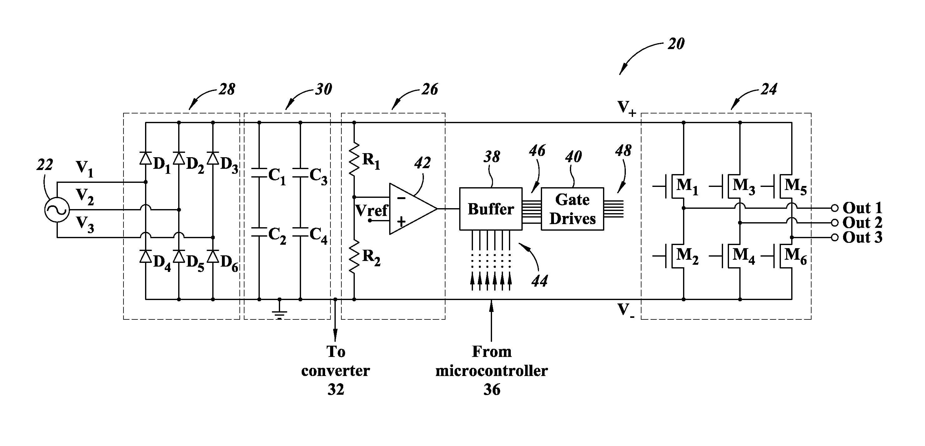
Figure 1 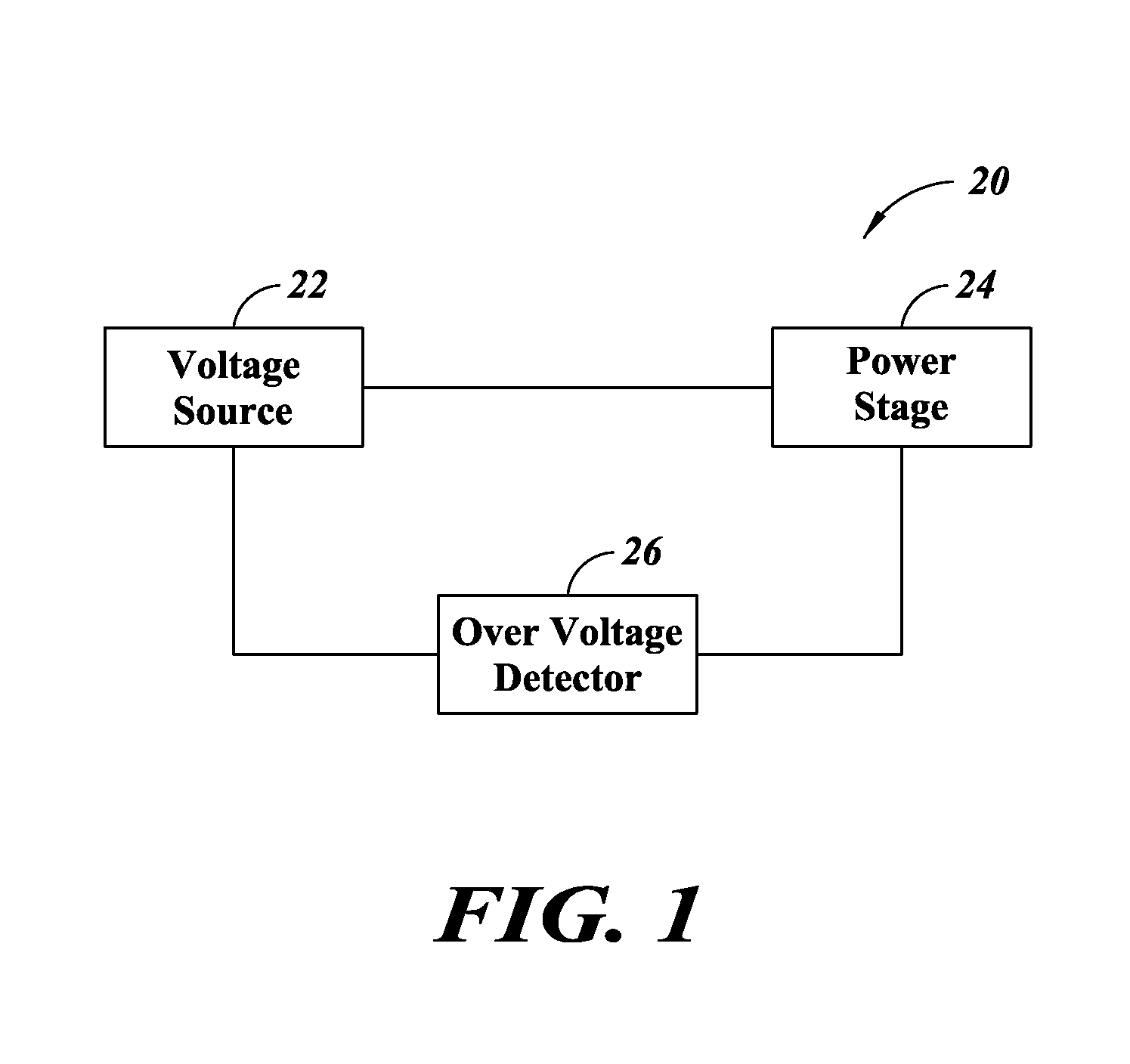
Figure 2 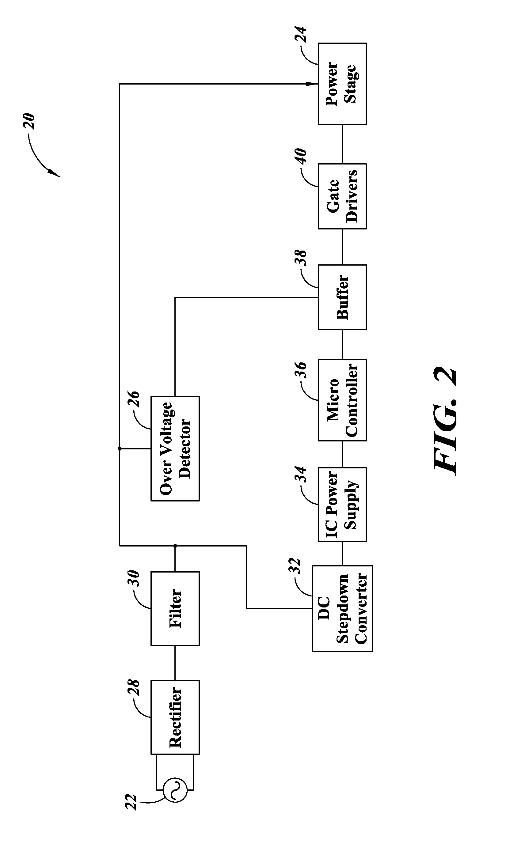
Figure 3
Abstract
Description
BACKGROUND
[0001] Technical Field
[0002] The present disclosure relates to the field of overvoltage protection and, more particularly, to in situ overvoltage protection for active bridge applications.
[0003] Description of the Related Art
[0004] Active switches such as MOS transistors, bipolar transistors, and IGBTs are used in bridge circuits for controlled rectification and inverter stages.
[0005] One common type of bridge circuit is the H-bridge. The H-bridge is formed by connecting two half bridges in parallel. Typically, each half bridge includes two active switches in series. A 3-phase bridge, typically used in brushless DC motor control, is formed by connecting three half bridges in parallel.
[0006] In applications where AC mains are rectified and filtered to generate a DC bus voltage supply for powering the active bridge inverter, overvoltage protection schemes are typically employed to protect the bridge circuit and the load from overvoltage conditions on the AC main.
[0007] Existing met...
Examples
Embodiment Construction
[0016]FIG. 1 is a block diagram of a bridge circuit 20, according to one embodiment. The motor control circuit includes a voltage source 22 and a power stage 24 coupled to the voltage source 22. The bridge circuit 20 further includes an overvoltage detector 26 coupled to the voltage source 22 and the power stage 24.
[0017]The voltage source 22 outputs a supply voltage to the power stage 24. In one embodiment the supply voltage is a DC voltage. Alternatively, the supply voltage can be an AC voltage such as a two phase or three phase voltage.
[0018]The power stage 24 receives the supply voltage and provides one or more output voltages. In one embodiment, the bridge circuit includes one or more half bridge circuits each including a pair of switches connected in series. The output voltages of the bridge circuit can include voltages present at the midpoint of each half bridge. The output voltages can be supplied to a load, such as a motor. In this way, the power stage 24 can drive the moto...