
Method of bonding substrates, microchip and method of manufacturing the same
Patent Information
- Authority / Receiving Office
- US · United States
- Current Assignee / Owner
- Publication Date
- 2018-05-24
Smart Images
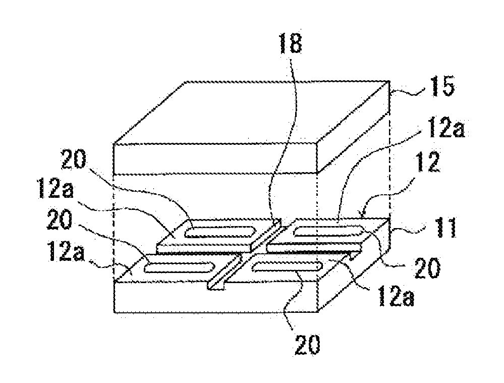
Figure 1 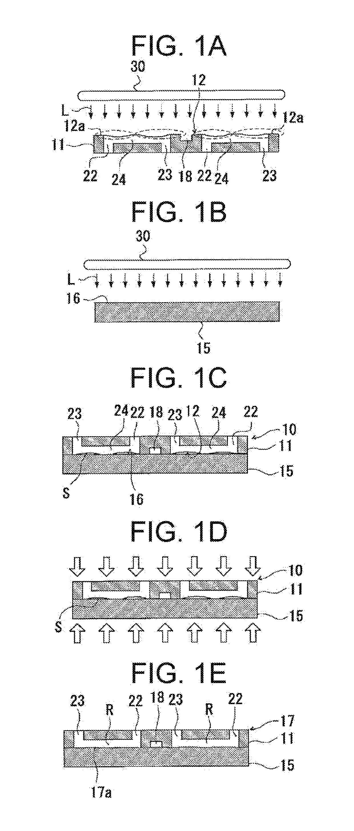
Figure 2 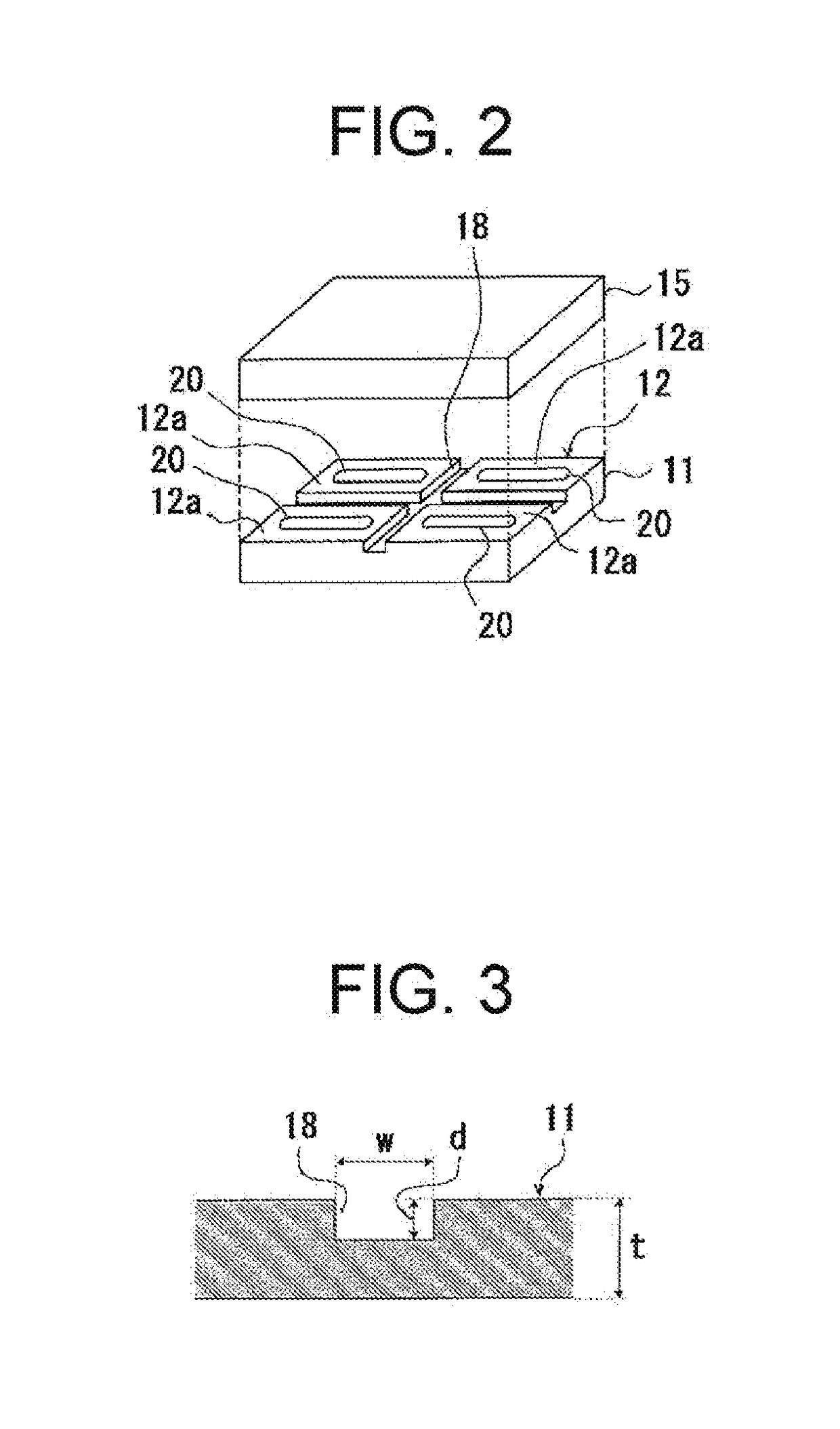
Figure 3
Abstract
Description
FIELD OF THE INVENTION
[0001] The present invention relates to a method of bonding two substrates, a microchip and a method of manufacturing the microchip.DESCRIPTION OF THE RELATED ART
[0002] Recent years, in a field of biochemistry, a certain technique that uses a microreactor for separating, synthesizing, extracting or analyzing a slight amount of reagent has been drawing an attention. This kind of microreactor is constituted with a microchip in which an analytical channel in microscale or the like is formed by use of a semiconductor micro fabrication technique on a small substrate made of, for example, silicon, silicon resin, or glass or the like.
[0003] A reaction analysis system using this kind of microreactor is called a Micro Total Analysis System (hereinafter referred to as “pTAS”). By using the pTAS, it makes it possible to perform the reaction analysis at a high speed with a high accuracy due to the fact that the ratio of a surface area thereof with respect to the volume of the...
Examples
working examples
[0172]Hereinafter, working examples of the method of bonding substrates according to the present embodiment will be described in detail below. Nevertheless, it should be noted that the present invention is not limited to the following working examples.
working example 1
[0173]The first substrate and the second substrate were prepared as follows.
[0174]FIG. 7 is a view illustrating the first substrate prepared according to the working example 1. A first substrate 41A has a profile conforming to the SBS standard (i.e., 85 mm×128 mm). On one face of a plate having the thickness of 2 mm and made of the cycloolefin resin (“ZEONEX 460R” manufactured by ZEON Corporation), a peripheral recessed portion 49A and a segmenting groove 48A are formed by the injection molding. The peripheral recessed portion 49A and the segmenting groove 48A are formed such that six rectangular joining regions 42aA, each having a profile of 36 mm×36 mm, are residually arranged as convex portions in two lines and three columns in parallel longitudinally and transversely.
[0175]The segmenting groove 48A has the width of 2 mm and the depth (that is, the distance from the joining regions 42aA to the innermost portion of the segmenting groove 48A) of 1 mm. Likewise, the peripheral reces...
working example 2
[0180]Two substrates were joined and the joined body [B] were obtained similarly to the working example 1, except that the first substrate was prepared as follows.
[0181]FIG. 8 is a view illustrating the first substrate prepared according to the working example 2. A first substrate 41B has a profile conforming to the SBS standard (i.e., 85 mm×128 mm). On one face of a plate having the thickness of 2 mm and made of the cycloolefin resin (“ZEONEX 460R” manufactured by ZEON Corporation), a peripheral recessed portion 49B and a segmenting groove 48B are formed by the injection molding. The peripheral recessed portion 49B and the segmenting groove 48B are formed such that twelve elongated rectangular joining regions 42aB, each having a profile of 18 mm×36 mm, are residually arranged as convex portions in two lines and six columns in parallel longitudinally and transversely.
[0182]The segmenting groove 48B has the width of 2 mm and the depth (that is, the distance from the joining regions 4...