
Infrared can curing oven
Patent Information
- Authority / Receiving Office
- US · United States
- Current Assignee / Owner
- Publication Date
- 2020-03-12
Smart Images
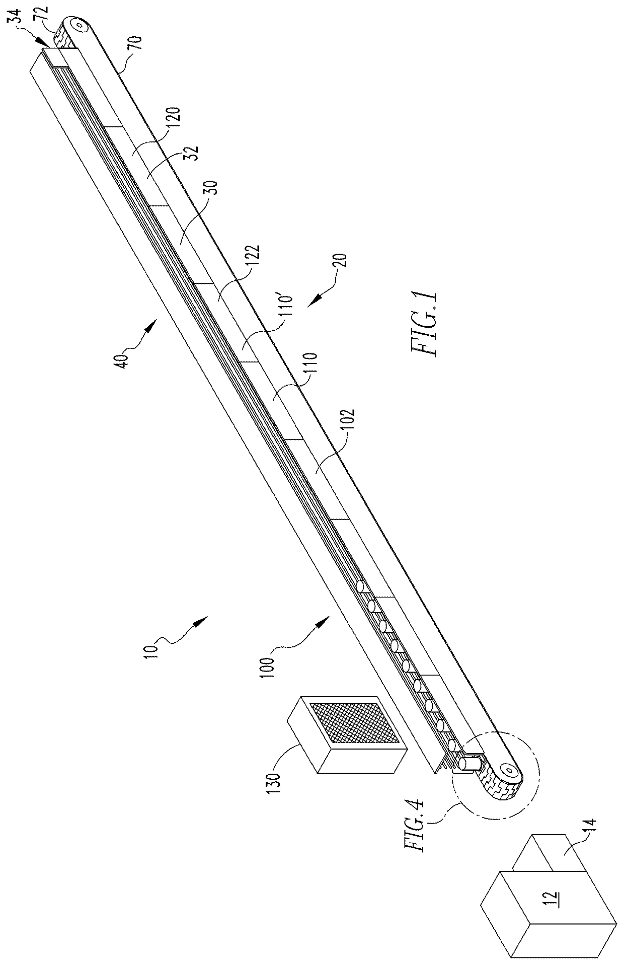
Figure 1 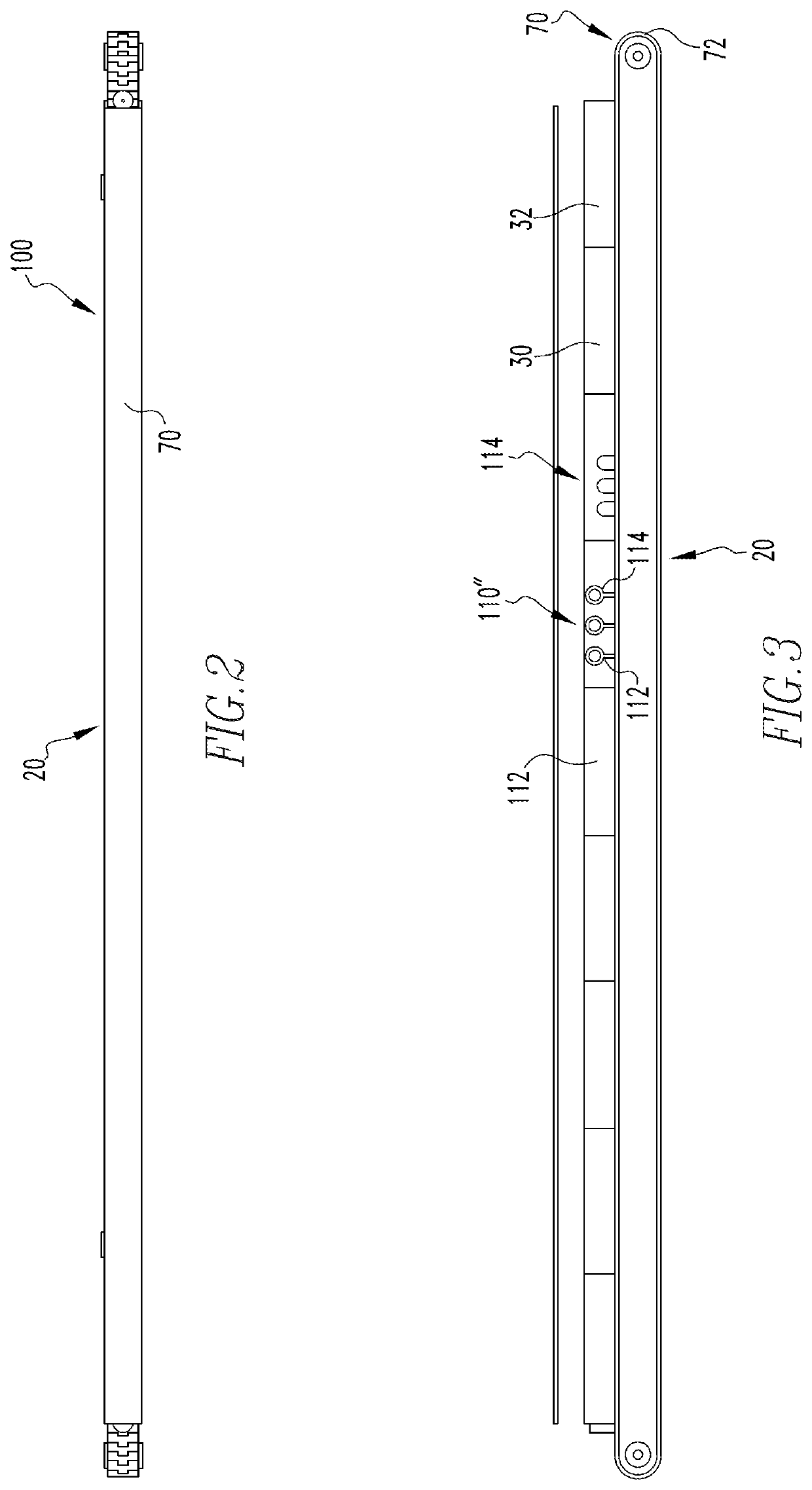
Figure 2 
Figure 3
Abstract
Description
BACKGROUND OF THE INVENTIONField of the Invention
[0001] The disclosed and claimed concept relates to an oven for drying a coating on the exterior of a can and, more particularly, to an oven that utilizes infrared heating units.Background Information
[0002] Pin ovens are well known in the art and are widely used in the industry for drying the coating on the exterior of partially completed, open-ended beverage cans. A can decorator applies the coating to the exterior of the cans. The coating includes, but is not limited to, ink, enamel used to apply the label, an overcoat of lacquer or varnish, or both a printed label and overcoat. The oven includes a number of heaters, typically natural gas heaters, that generate a heated fluid (air). That is, natural gas is burned thereby heating the air. The heated air is generally maintained in a heated, enclosed space through which a conveyor chain follows a generally vertical serpentine path. As such, pin ovens occupy a large volume and have a comp...
Examples
Embodiment Construction
[0016]It will be appreciated that the specific elements illustrated in the figures herein and described in the following specification are simply exemplary embodiments of the disclosed concept, which are provided as non-limiting examples solely for the purpose of illustration. Therefore, specific dimensions, orientations, assembly, number of components used, embodiment configurations and other physical characteristics related to the embodiments disclosed herein are not to be considered limiting on the scope of the disclosed concept.
[0017]Directional phrases used herein, such as, for example, clockwise, counterclockwise, left, right, top, bottom, upwards, downwards and derivatives thereof, relate to the orientation of the elements shown in the drawings and are not limiting upon the claims unless expressly recited therein.
[0018]As used herein, the singular form of “a,”“an,” and “the” include plural references unless the context clearly dictates otherwise.
[0019]As used herein, “structu...