
Screw structure
Patent Information
- Authority / Receiving Office
- US · United States
- Current Assignee / Owner
- Publication Date
- 2020-10-22
- Estimated Expiration
- Not applicable · inactive patent
Smart Images
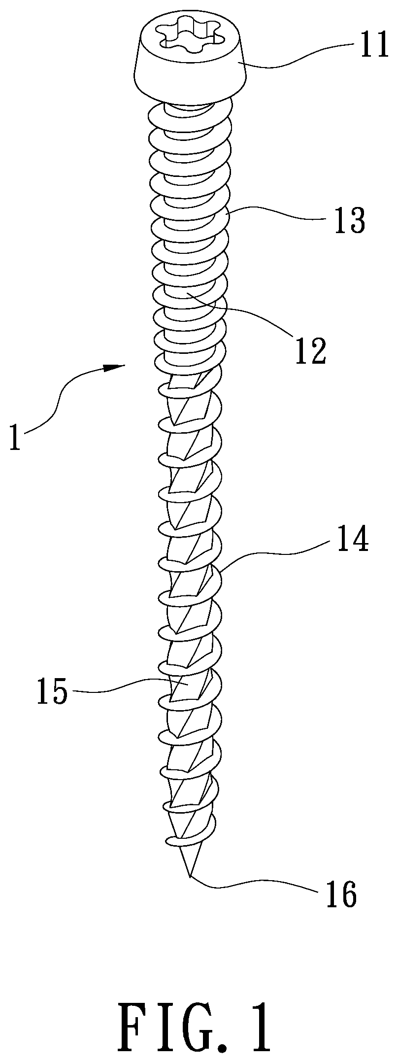
Figure 1 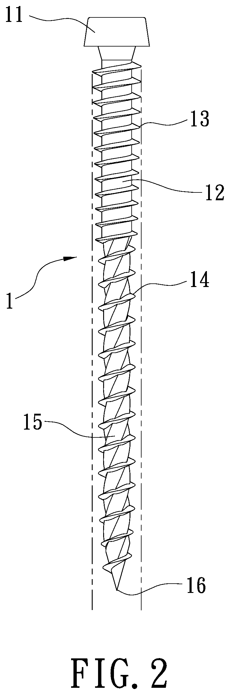
Figure 2 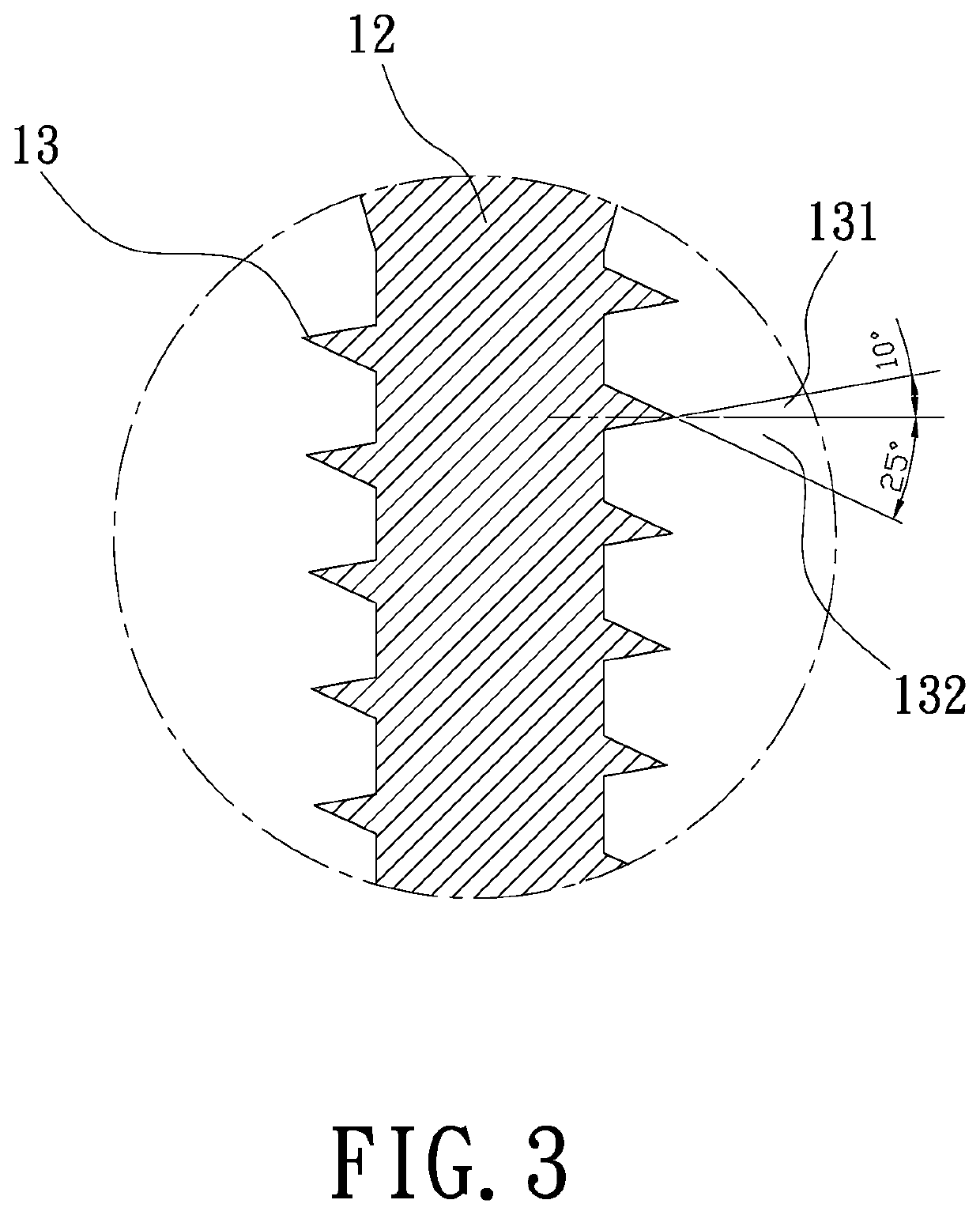
Figure 3
Abstract
Description
BACKGROUND OF THE INVENTION1. Field of the Invention
[0001] The present invention relates to a screw structure which can prevent the wood shavings from splashing outward to reduce the environmental mess, increase the adhesion between a screw and a wood material to achieve an excellent anti-loose effect, and reduce the resistance of the drilling to increase the smoothness of the drilling process so that it can be applied to screw into various wood materials to decrease the occurrence of wood cracking or screw breakage and save time and effort during use.2. Description of Related Art
[0002] Generally, the screws have different functions according to different thread arrangements, screw lengths and pitches. A common screw structure comprises an integrally formed head, a rod body, a beveling tangent screw thread wrapping on a periphery of the rod body, and a tip. The head is formed at one end of the rod body, and the tip is formed at the other end of the rod body. In this way, the head driv...
Examples
Embodiment Construction
[0011]Hereinafter, an exemplary embodiment of the present invention will be described in detail with reference to the accompanying drawings.
[0012]As showed in FIG. 1 and FIG. 2, a stereogram and a cross-sectional view of a screw structure according to the present invention are respectively disclosed herein. A screw (1) comprises a head (11), a rod part (12), an upper thread part (13), a lower thread part (14), a plurality of beveling tangent planes (15) and a tip (16). The head (11) of the screw (1) can be rotated by various hand tools, electric tools and the like to screw into an object. The rod part (12) is connected at a lower end of the head (11). The upper thread part (13) is formed on a periphery of an upper portion of the rod part (12) and has plural thread pitches. Referring to FIG. 3, the upper thread part (13) forms a first lead angle (131) of 5-15 degrees (preferably 10 degrees) between a first line extending upward from a lower edge thereof and a vertical line of the rod...