
Power transformer/inductor
Patent Information
- Authority / Receiving Office
- US · United States
- Current Assignee / Owner
- Publication Date
- 2005-11-29
- Estimated Expiration
- Not applicable · inactive patent
Smart Images
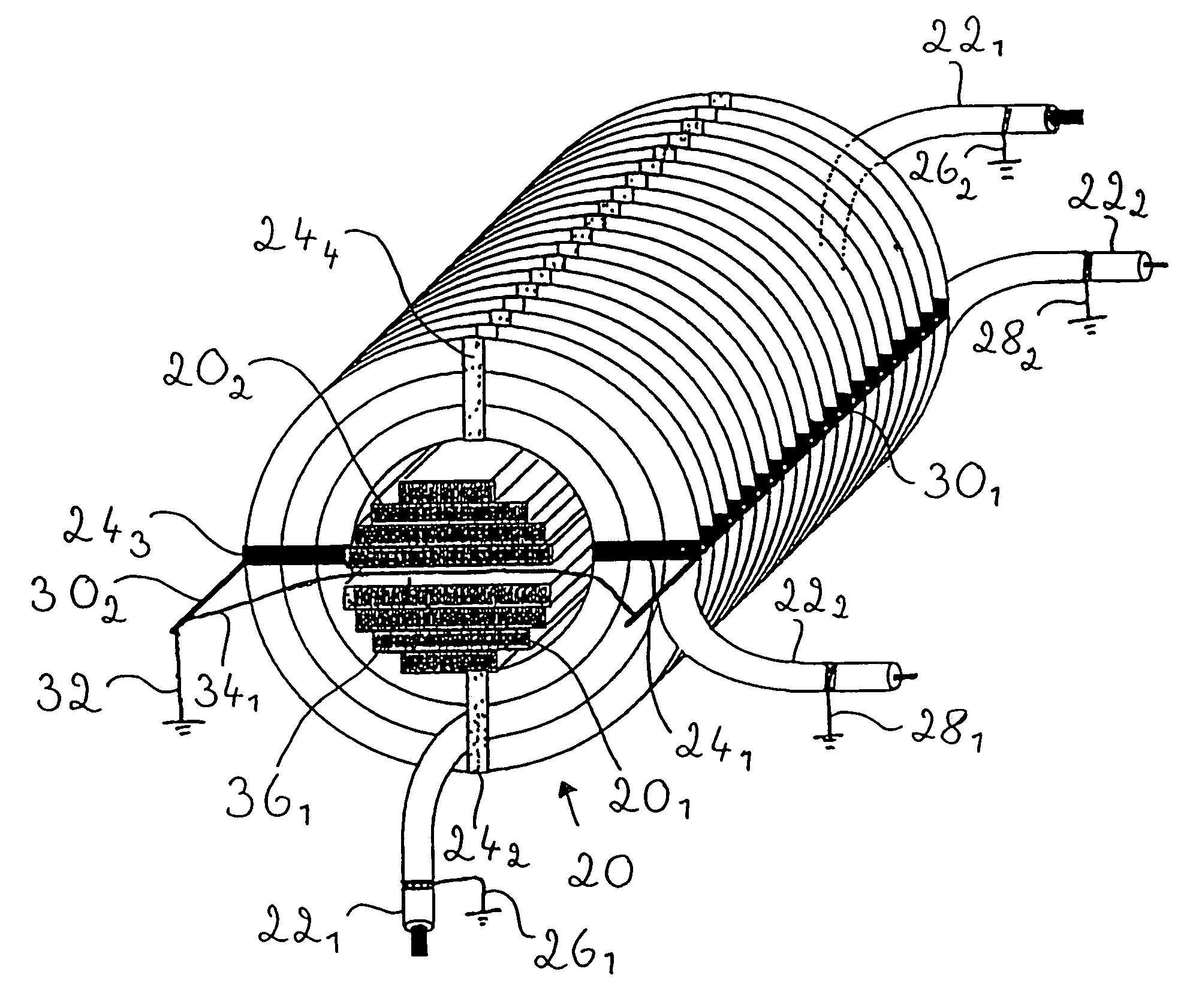
Figure 1 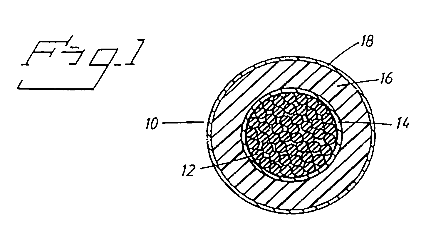
Figure 2 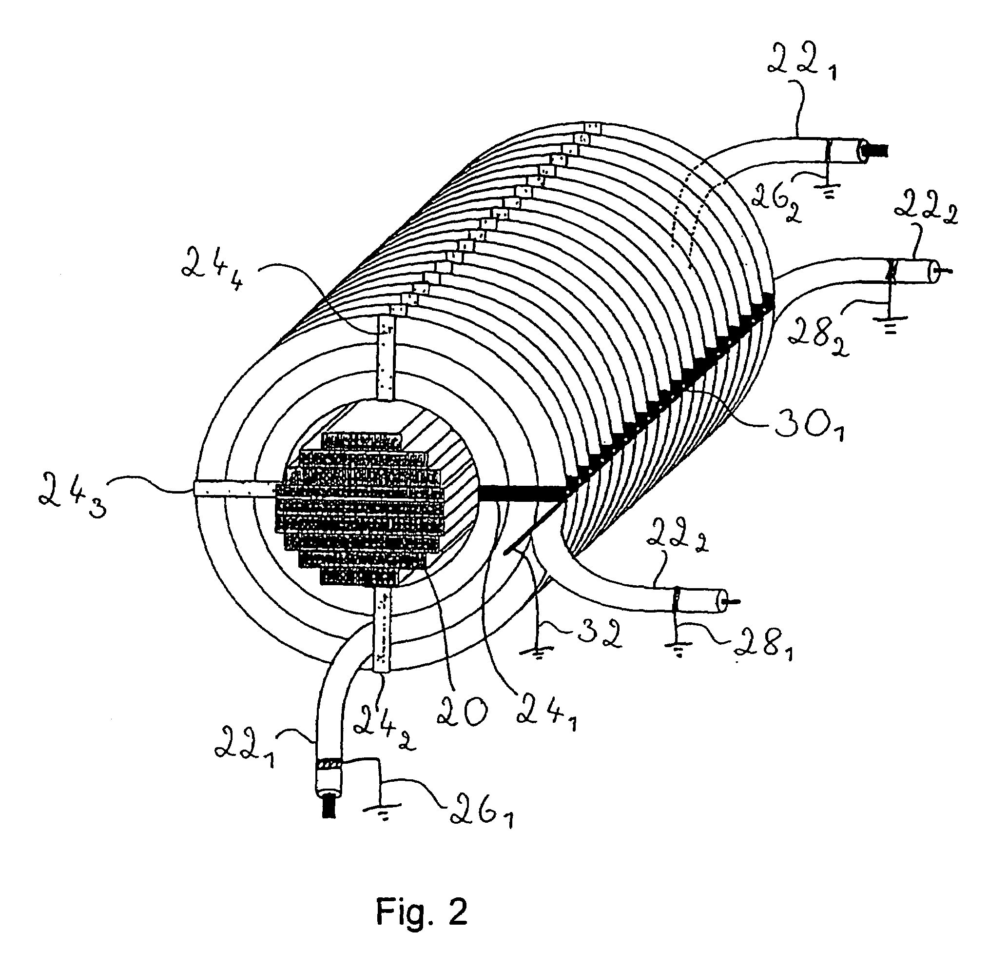
Figure 3
Abstract
Description
BACKGROUND OF THE INVENTION
[0001] 1. Field of the Invention
[0002] The present invention relates to a power transformer / inductor. In all transmission and distribution of electric energy, transformers are used for enabling exchange between two or more electric systems normally having different voltage levels. Transformers are available for powers from the VA region to the 1000 MVA region. The voltage range has a spectrum of up to the highest transmission voltages used today. Electro-magnetic induction is used for energy transmission between electric systems.
[0003] Inductors are also an essential component in the transmission of electric energy in for example phase compensation and filtering.
[0004] The transformer / inductor related to the present invention belongs to the so-called power transformers / inductors having rated outputs from several hundred kVA to in excess of 1000 MVA and rated voltages of from 3–4 kV to very high transmission voltages.
[0005] 2. Discussion of the Background
[0006] I...
Examples
first embodiment
[0046]FIG. 3 shows a perspective view of windings with two earthing points per winding turn according to the present invention. In FIGS. 2 and 3 the same parts are designated by the same numerals in order to make the Figures more clear. Also in this case the two windings 221 and 222, formed from the high-voltage cable 10 shown in FIG. 1, are arranged around the core leg 20. Spacer member 241, 242, 243, 244 are also in this case radially arranged with the aim of fixing the windings 221 and 222. At both ends 261, 262, 281, 282 of each winding 221 and 222 the second semiconducting layer (compare with FIG. 1) is earthed in accordance with FIG. 2. Spacer members 241, 243, which are marked in black, are used in order to achieve two earthing points per winding turn. Spacer member 241 is directly connected to a first earthing element 301 and spacer member 243 is directly connected to a second earthing element 302 at the periphery of the winding 222 and along the axial length of the winding ...
second embodiment
[0047]FIG. 4 shows a perspective view of windings with three earthing points per winding turn according to the present invention. In FIGS. 2–4 the same parts are designated by the same numerals in order to make the Figures more clear. Also here two windings 221 and 222, formed from the high-voltage cable 10 shown in FIG. 1, are arranged around the core leg 20. Spacer members 241, 242, 243, 244, 245, 246, are also radially arranged with the aim of fixing windings 221 and 222. As shown in FIG. 4 there are 6 spacer members per winding turn. At both ends 261, 262; 281, 282 of each winding 221, 222 the outer semiconducting layer (compare with FIG. 1) is earthed as in accordance with FIGS. 2 and 3. Spacer members 241, 243, 245 which are marked in black are used to achieve three earthing points per winding turn. These spacer members 241, 243, 245 are accordingly connected to the second semiconducting layer of the high power cable 10. Spacer member 241 is directly connected to a first earth...
third embodiment
[0048]FIGS. 5a and 5b respectively, show a perspective view respectively and a sectional view of a winding on an outer leg of a three phase transformer with three legs with three earthing points per winding turn according to the present invention. In FIGS. 2–5 the same parts are designated the same numerals in order to make the Figures more clear. A winding 221, formed from the high-voltage cable 10 shown in FIG. 1, is arranged around the outer leg 20 of the transformer. Additionally in this case spacer members 241, 242, 243, 244, 245, 256 are arranged radially with the aim of fixing the winding 221. At both ends of the winding 222 the second semiconducting layer (compare with FIG. 1) is earthed (not shown in FIGS. 5a and 5b respectively). Spacer members 241, 243, 245, which are marked in black, are used to achieve three earthing points per winding turn. Spacer member 241 is directly connected to a first earthing element 301, spacer member 243 is directly connected to a second earth...