
Color splitting/combining optical system and image projecting apparatus
Patent Information
- Authority / Receiving Office
- US · United States
- Current Assignee / Owner
- Publication Date
- 2006-11-21
- Estimated Expiration
- Not applicable · inactive patent
Smart Images
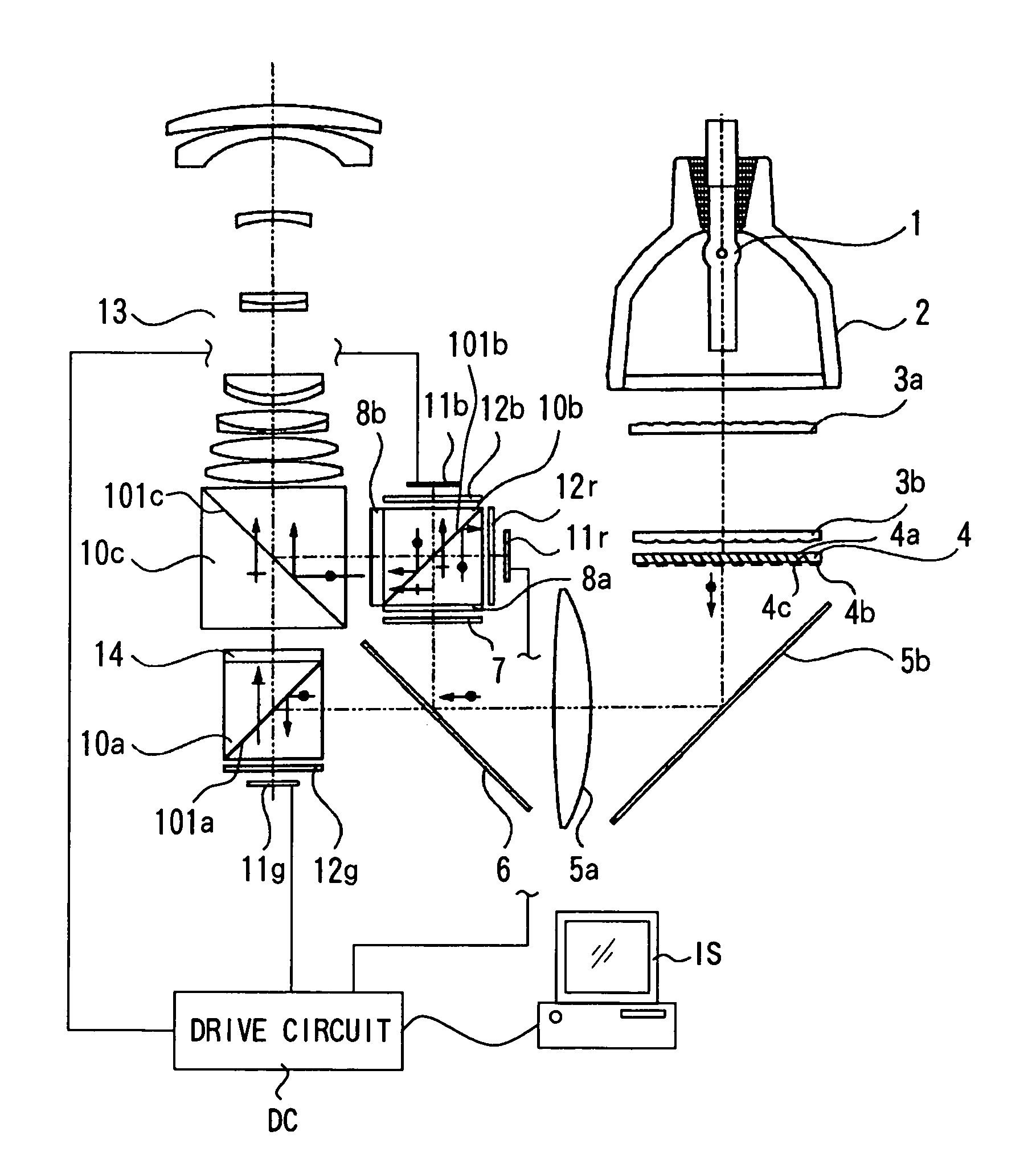
Figure 1 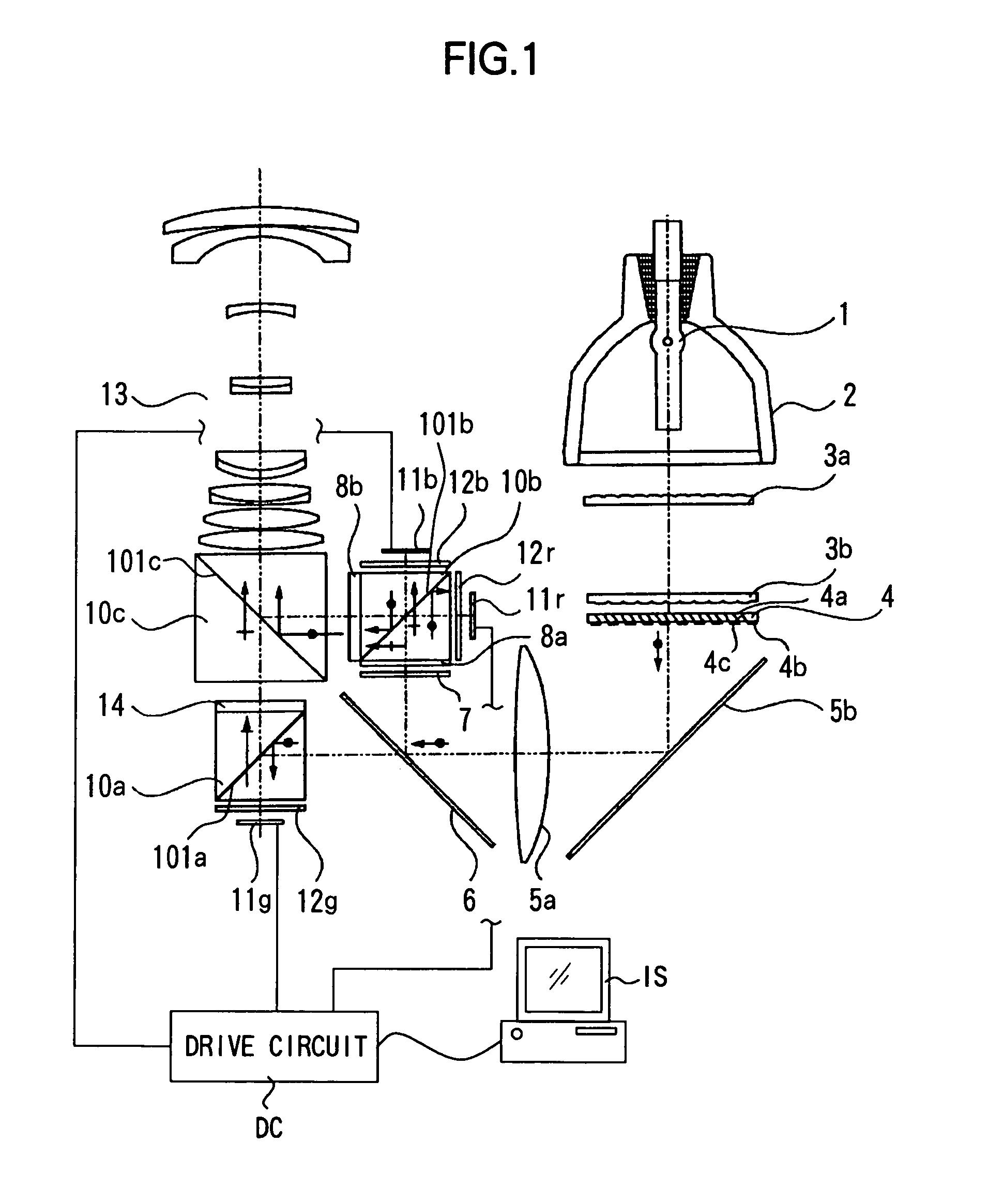
Figure 2 
Figure 3
Abstract
Description
BACKGROUND OF THE INVENTION
[0001] 1. Field of the Invention
[0002] The present invention relates to a color splitting / combining optical system used for an image projection apparatus (projector) for projecting light from image-forming elements which form an original picture.
[0003] 2. Description of Related Art
[0004] An image projection apparatus in which reflection type liquid crystal display elements and a polarization beam splitter are combined with each other is disclosed by Japanese Patent Application Laid-open No. 2001-154268. The corresponding image projection apparatus is an image projection apparatus having a white-color light source 1001, reflection type liquid crystal display elements 1002R, 1002G and 1002B, and a projection optical system 1003 as shown in FIG. 33. In the corresponding image projection apparatus, a dichroic mirror 1004 is provided between the white-color light source 1001 and the reflection type liquid crystal display elements 1002R, 1002G and 1002B. Further, th...
Examples
embodiment 1
(Embodiment 1)
[0072]FIG. 1 is a view representing Embodiment 1 according to the present invention. In the drawing, Reference Numeral 1 denotes a light source which emits white-color light with a continuous spectrum. Reference Numeral 2 denotes a reflector which condenses light in a predetermined direction. Reference Numeral 3a denotes a first fly-eye lens having rectangular lenses disposed in a matrix state, and 3b denotes a second fly-eye lens constituted by lens arrays corresponding to respective lenses of the first fly-eye lens.
[0073]Reference Numeral 4 denotes a polarization converting element which makes non-polarized light into predetermined polarized light. Reference Numeral 5a denotes a condenser lens and 5b denotes a mirror. Reference Numeral 6 denotes a dichroic mirror which is a first optical member, which reflects light components of wavelength regions of blue (B) and red (R) and transmits a light component of a wavelength region of green (G).
[0074]Reference Numeral 7 de...
embodiment 2
(Embodiment 2)
[0093]FIG. 4 is a view representing Embodiment 2 according to the present invention, wherein parts which are identical to those in Embodiment 1 are given the same Reference Numerals. A point in which Embodiment 2 differs from Embodiment 1 resides in that the arrangement of the reflection type liquid crystal display element for R and the reflection type liquid crystal display element for B is reversed. Therefore, in Embodiment 2, the first color-selective wave plate 28a which converts the polarization direction of the light component of R by 90 degrees but does not convert the polarization direction of the light component of B, and the second color-selective wave plate 28b which converts the polarization direction of the light component of B by 90 degrees but does not convert the polarization direction of the light component of R are provided.
[0094]FIG. 5 shows the characteristics of the first color-selective wave plate according to the present embodiment with thick lin...
embodiment 3
(Embodiment 3)
[0102]FIG. 6 is a view representing Embodiment 3 according to the present invention, wherein parts which are identical to those of Embodiment 1 are given the same Reference Numerals. A point in which Embodiment 3 differs from Embodiment 1 resides in that Embodiment 3 is provided with a polarization converting element 34 by which non-polarized light is aligned to be P-polarized light. Therefore, a first color-selective wave plate 38a which converts the polarization direction of the light component of R by 90 degrees but does not convert the polarization direction of the light component of B, and a second color-selective wave plate 38b which rotates the polarization direction of the light component of R by 90 degrees but does not convert the polarization direction of the light component of B are provided therein, and the ½ wave plate 31 which converts the polarization direction of light G by 90 degrees is provided at the incidence side of the first polarization beam spli...