
Integrated air supply with humidification control for fuel cell power systems
a fuel cell power system and air supply technology, applied in the field of manipulating airflow, can solve the problems of reducing the hydration level of the membrane, limiting the electrical conductivity of the membrane, and no guarantee of local water balance, so as to reduce the number of components, reduce the complexity of the concomitant device, and reduce the loss of individual or similar dedicated conduits
Patent Information
- Authority / Receiving Office
- US · United States
- Patent Type
- Patents(United States)
- Current Assignee / Owner
- Publication Date
- 2009-09-22
- Estimated Expiration
- Not applicable · inactive patent
Smart Images
Figure 1 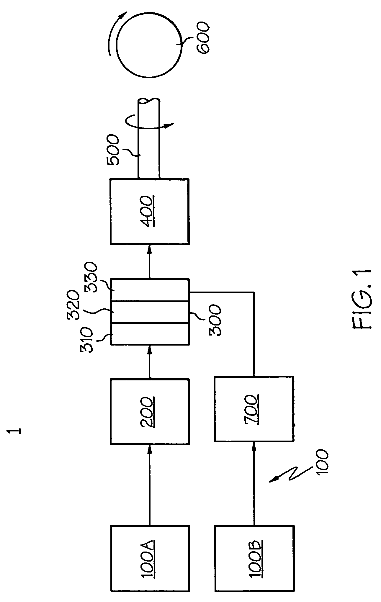
Figure 2 
Figure 3
Abstract
Description
BACKGROUND OF THE INVENTION
[0001] The present invention relates generally to manipulating airflow for use as a reactant in a fuel cell system, and more particularly to integrating air supply system components in such a way as to reduce the size, weight and complexity associated with such airflow manipulation.
[0002] While conventional power source devices (such as internal combustion engines, including piston and gas turbine-based platforms) are well-known as ways to produce, among other things, motive, heat and electric power, recent concerns about the effects they and their fuel sources have on the environment have led to the development of alternative means of producing such power. The interest in fuel cells is in response to these and other concerns. One form of fuel cell, called the proton exchange membrane (PEM) fuel cell, has shown particular promise for vehicular and related mobile applications, using hydrogen and oxygen as the primary reactants to produce electricity with wate...
Examples
Embodiment Construction
[0024]Referring initially to FIGS. 1 and 4, a block diagram highlights the major components of a mobile fuel cell system 1 according to the present invention, as well as a representative placement of a fuel cell system into an automotive application. Referring with particularity to FIG. 1, the system 1 includes a fuel delivery system 100 (made up of fuel source 100A and oxygen source 100B), fuel processing system 200, fuel cell 300, one or more energy storage devices 400, a drivetrain 500 and one or more motive devices 600, shown notionally as a wheel. While the present system 1 is shown for mobile (such as vehicular) applications, it will be appreciated by those skilled in the art that the use of the fuel cell 300 and its ancillary equipment is equally applicable to stationary applications. It will also be appreciated by those skilled in the art that other fuel delivery and fuel processing systems are available. For example, there could be, in addition to a fuel source 100A and oxy...